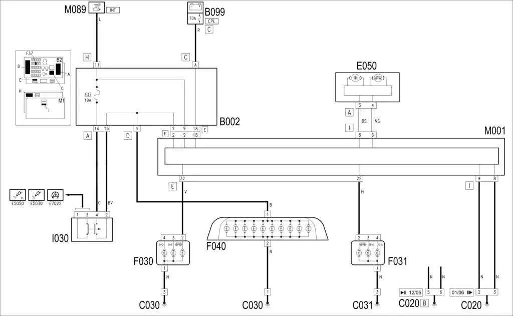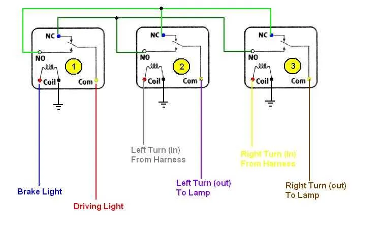
Start by ensuring the correct placement of the power source and grounding connection. Proper grounding is essential to prevent electrical surges that could damage the components of the signaling system. Check for a solid connection to the vehicle’s chassis and verify it with a multimeter. Any weak or intermittent grounding can lead to malfunctions in the system.
The next step is to establish a secure link between the control switch and the rear components. Use appropriately sized wires, ensuring they are rated for the current required by the system. For most vehicles, this means wires with at least a 14 AWG rating for safe operation. Make sure to use high-quality connectors that prevent corrosion and ensure a stable connection over time.
When connecting the power leads to the rear units, ensure that each circuit is properly fused. This adds an extra layer of protection against short circuits or overloads. Place the fuse as close to the power source as possible to limit the risk of damage in the event of a fault. The fuse rating should match the specifications outlined by the manufacturer for optimal protection.
Finally, test the system with the vehicle’s electrical controls, verifying that the rear signals activate as expected. If any issue arises, inspect the wiring and connections for signs of wear or poor contact. It’s crucial to address these issues promptly to maintain safety while driving.
How to Set Up Your Vehicle’s Signal System
For proper installation of the vehicle’s rear signaling system, start by identifying the power source. The circuit must be connected to a reliable 12V supply, usually accessed from the fuse box. Ensure the connection is properly fused to prevent overloads.
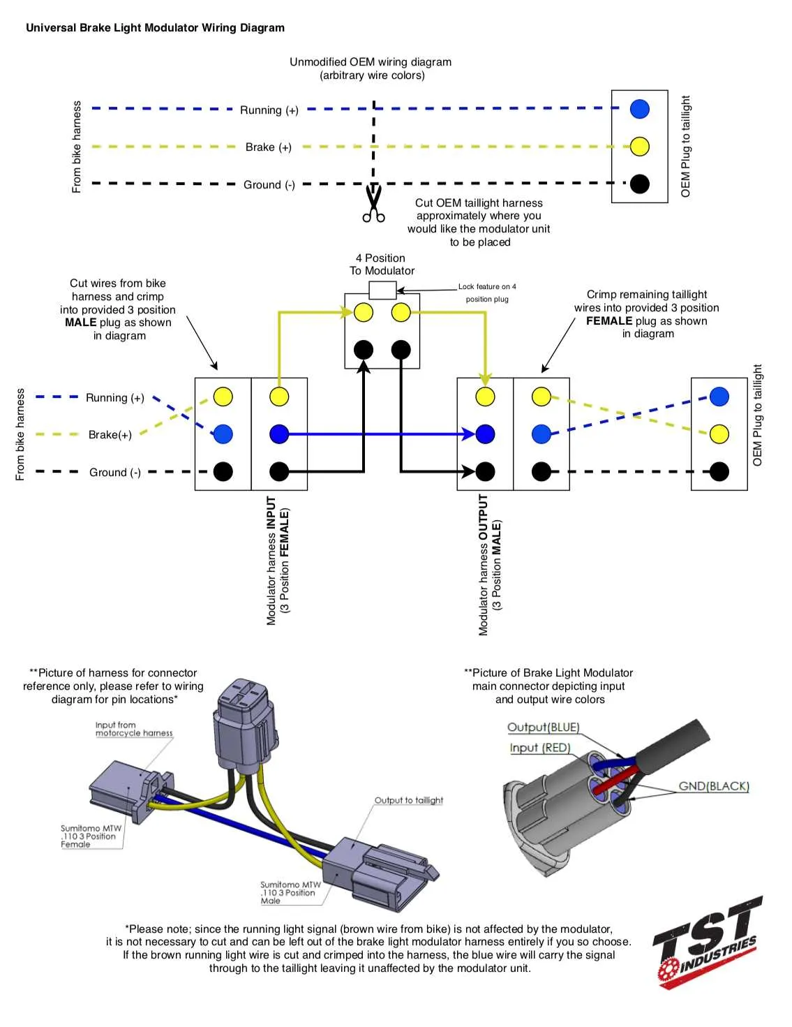
Next, connect the positive wire from the power source to the input terminal of the signaling unit. The ground wire should be connected securely to the vehicle’s chassis to establish a complete circuit.
Once the input is wired, attach the output terminals to the appropriate connectors of the rear units. The left and right signal units typically require separate leads to avoid cross-interference. Check that the connectors are properly insulated to prevent short circuits.
Test the functionality by activating the signal system. If the units are not responding as expected, check the connections and ensure the terminals are clean and free from corrosion. A multimeter can be used to test the current flow along each lead to ensure the proper voltage is reaching the components.
Pro tip: Use color-coded wires for easy identification during troubleshooting or future repairs. Red is commonly used for positive connections, while black typically serves as the ground. Always ensure the wire insulation is intact to prevent shorting.
In case of failure, inspect the fuses and replace them if necessary. Verify the wiring is free of damage, especially at bends or areas exposed to friction. The proper installation ensures safe and effective operation of the signaling units.
How to Identify and Test Circuit Components for Rear Signal Activation

Start by verifying the power supply to the system. Ensure the fuse linked to the signal system is intact. If blown, replace it with a fuse of the same amperage. Check the voltage at the connection point of the system. You should see around 12V when the system is activated.
- Testing the Switch: Locate the switch that controls the activation of the system. It’s usually near the pedal or lever. Use a multimeter to check for continuity when the pedal or lever is pressed. A working switch will show a closed circuit.
- Inspecting the Sensor: The sensor ensures the activation signal reaches the component. Inspect the wiring to ensure it is not frayed or disconnected. To test, apply power directly to the sensor; if the system engages, the sensor is functional.
- Examining the Relay: The relay directs current to the activation components. Using a multimeter, check the relay’s coil for resistance. If no resistance is detected, replace the relay. A functional relay should provide an audible click when activated.
- Confirming the Connections: Inspect the connectors along the circuit. Any loose or corroded connections can disrupt the flow of electricity. Clean and tighten all connections to ensure proper functionality.
If all components test correctly but the system still does not function, check the ground connection. A faulty or poor ground can prevent the activation signal from completing its circuit.
Step-by-Step Guide to Troubleshooting Brake Light Wiring Issues

1. Check the fuse. If the fuse connected to the signaling system is blown, replace it with a new one of the same rating.
2. Inspect the bulb socket. Corrosion or loose connections can prevent proper contact. Clean the contacts or replace the socket if necessary.
3. Test the switch. Ensure the switch operates properly when the pedal is pressed. If it’s faulty, replace it to restore functionality.
4. Examine the grounding. A poor ground connection can cause intermittent operation. Ensure the ground wire is securely attached to a clean metal surface.
5. Inspect the connector. A broken or worn connector can interrupt the current flow. Check for loose or frayed connectors and repair or replace as needed.
6. Trace the circuit. Use a multimeter to identify any breaks or shorts along the path. Repair or replace damaged sections of the circuit.
7. Test the system after repairs. Once you’ve addressed all potential issues, check the system by pressing the pedal and confirming the activation of the signals.
Common Electrical Issues in Signal Systems and How to Resolve Them
To address malfunctioning indicators, check for loose or corroded connections. Ensure terminals are properly fastened to avoid intermittent issues. Inspect the ground wire; a poor connection here can prevent signals from activating.
If you notice flickering or dimming, the issue might stem from a faulty switch or insufficient voltage. Examine the switch for wear and replace it if necessary. Additionally, confirm the power supply is stable and can handle the load of the entire system.
Another frequent problem is blown fuses. If the fuse blows repeatedly, this could indicate a short circuit or an overloaded circuit. Inspect the entire pathway for exposed wires or damaged insulation that might cause a short. Replace any broken components and use the correct amperage fuse to avoid further issues.
Worn-out bulbs or defective sockets can also result in malfunctioning signals. Check for physical damage, such as cracks or corrosion, and clean or replace any compromised parts. When replacing bulbs, always opt for the recommended type and voltage.
Finally, poor electrical connections inside the junction box can lead to malfunction. Inspect the box for signs of rust or dirt, and ensure the connections are secure and free from debris. A simple cleaning and tightening can often restore proper function.