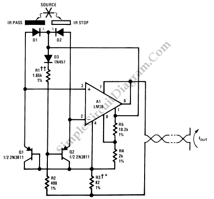
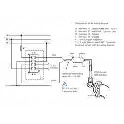
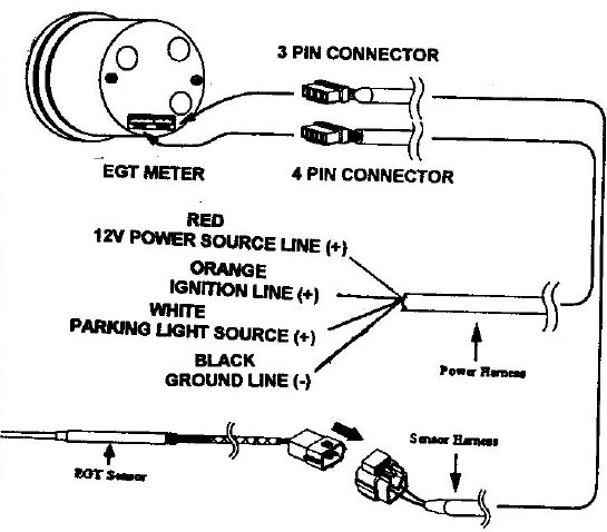
Diagram C. Proper wiring of the VDO Pyrometer.
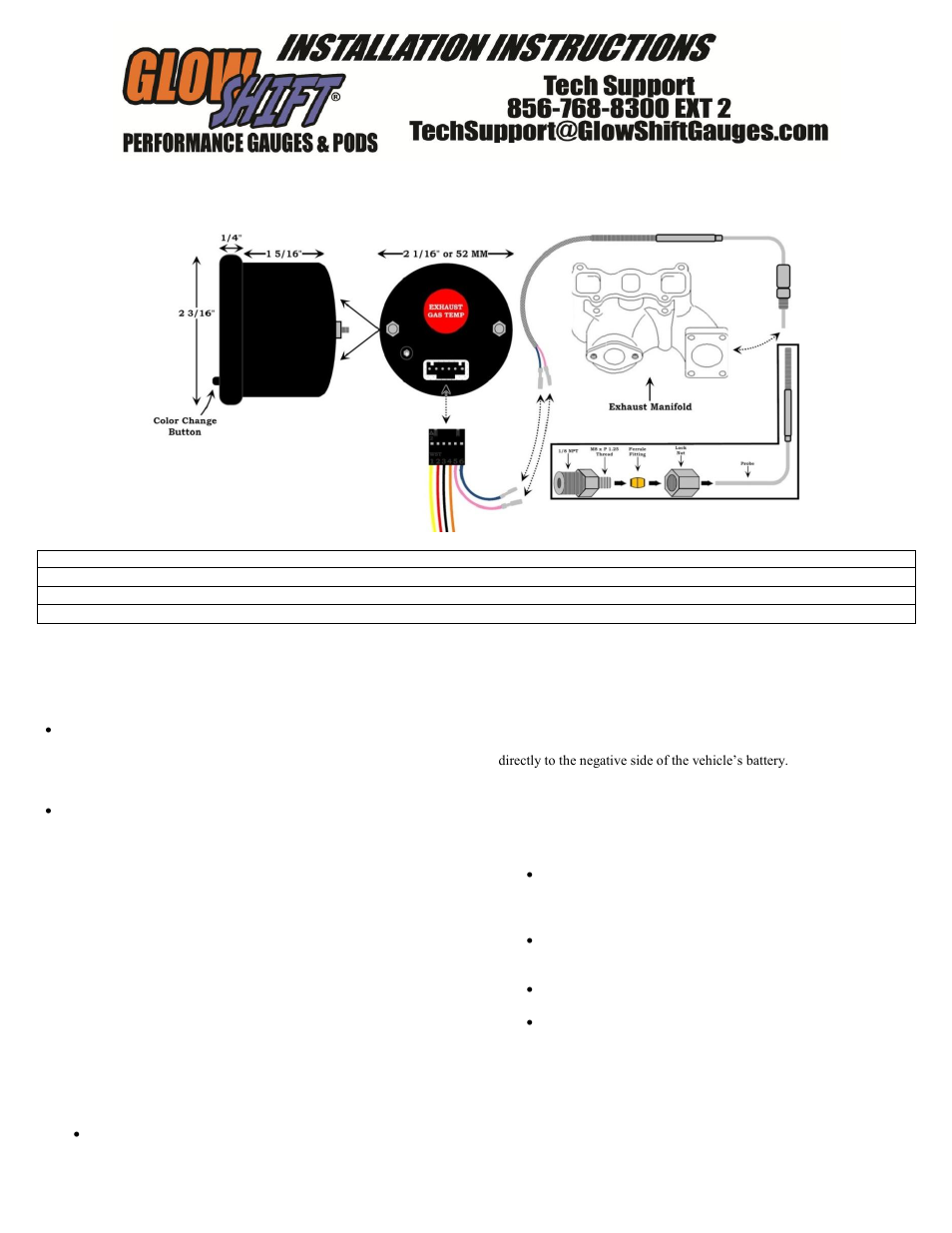
The bezel diameter is only a few mil- limeters larger than the gauge itself. With that in mind, measure and pre-. Refer to Installation Diagram.
A. Thermocouple ends – use crimp or clamp types only – NEVER solder terminals to the wires.
Dual Manifold with Single Gauge. wire movement.
Terminal connections to pyrometer are designed to insure correct polarity. Page 1 of 2.
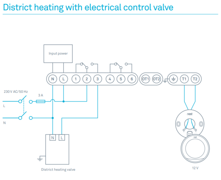
SINGLE PYROMETER WIRING DIAGRAM. Examples.
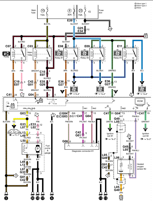
DIAGRAM 2. Wiring Installation Instructions for: PYROMETER.
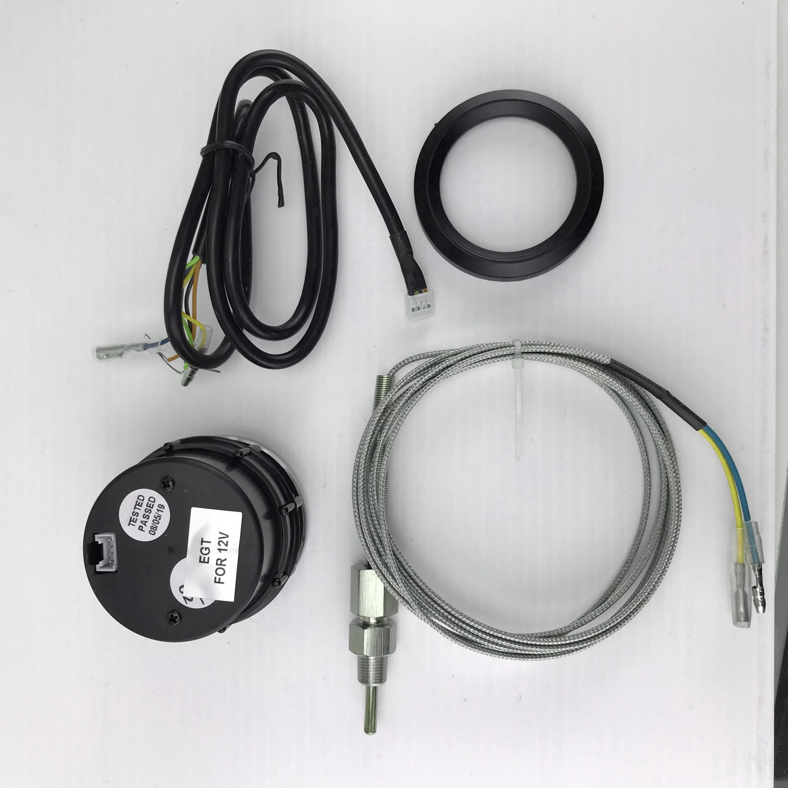
2 1/16” Spek Pro Professional Racing Gauge. Optional: Wiring a Relay for Gauge Controlled.
the wires do not come into contact with, or become too close to, the manifold or other hot engine parts. The extension wire is an integral part of the pyrometer calibration.
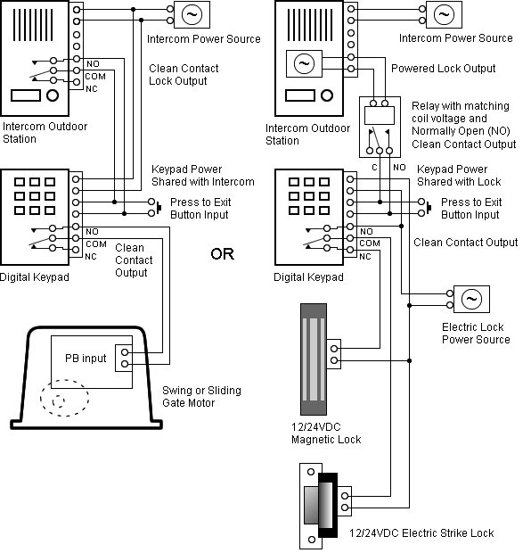
It may not Follow the diagram below to connect 12 volt lighting. See .Remote Start Wiring Diagrams For Unbelievable Diagram Isspro In Pyrometer.
On this website we recommend many images about Isspro Pyrometer Wiring Diagram that we have collected from various sites from many image inspiration, and of course what we recommend is the most excellent of image for isspro pyrometer wiring diagram. If you like the. Note – Use 18 AWG for wire harness Read these instructions thoroughly before installation.
Do not deviate from assembly or wiring diagram. Always disconnect battery ground before making any electrical connections.
IMPORTANT: Mounting dimensions vary for different gauges. Please be certain to follow the instructions for your specific gauge.
is removed during installation, lamp hole should be plugged or taped over to prevent dirt or metal particles from contaminating the movement. Thermocouple Installation: When installing pyrometers and thermocouples, thermocouple extension wire must be used to maintain the integrity and accuracy of the pyrometer.
Glowshift Wire Diagram
May 21, · Does anyone have a link to a basic pyrometer wiring diagram. The one in my truck really doesnt work at all (like that when I bought the truck) I wanna check all the schematron.org like there is no power going to it.
Isspro Pyrometer Wiring Diagram. Isspro Pyrometer Wiring Diagram. On this website we recommend many designs about Isspro Pyrometer Wiring Diagram that we have collected from various sites of Wiring Diagrams Collections, and of course what we recommend is the most excellent of design for Isspro Pyrometer Wiring schematron.org you like the design on our website, please do not hesitate to .Account SuspendedPyrometer wiring diagram.
– Diesel Forum – schematron.org