To ensure optimal performance of your V8 motor, it’s crucial to understand the specific routing of the air management system. The routing involves various components that manage pressure changes and air intake to support efficient combustion. Improper connections can lead to decreased engine efficiency and poor fuel economy.
The key to a smooth-running system is ensuring that each line is properly connected, with no leaks or blockages in the system. Start by confirming the locations of the various vacuum lines, especially those that control the throttle and brake booster. Any disruption in these lines can cause inconsistent engine behavior, affecting idle and throttle response.
Important Tips: Always replace worn or cracked hoses promptly. If you notice rough idling or hesitation during acceleration, inspect the vacuum hoses for potential damage. It’s also helpful to verify that the vacuum source is functioning correctly, as many components rely on consistent pressure to operate. Consulting your vehicle’s manual for specific pressure settings will help maintain accuracy in the system’s performance.
Remember, an intact air management network is fundamental for keeping your V8 running at peak performance. Regular maintenance, including the inspection of vacuum lines, can save you from more expensive repairs down the line.
Detailed Routing for the 5.0L V8 System

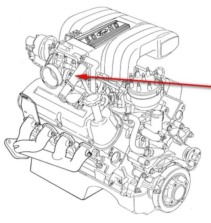
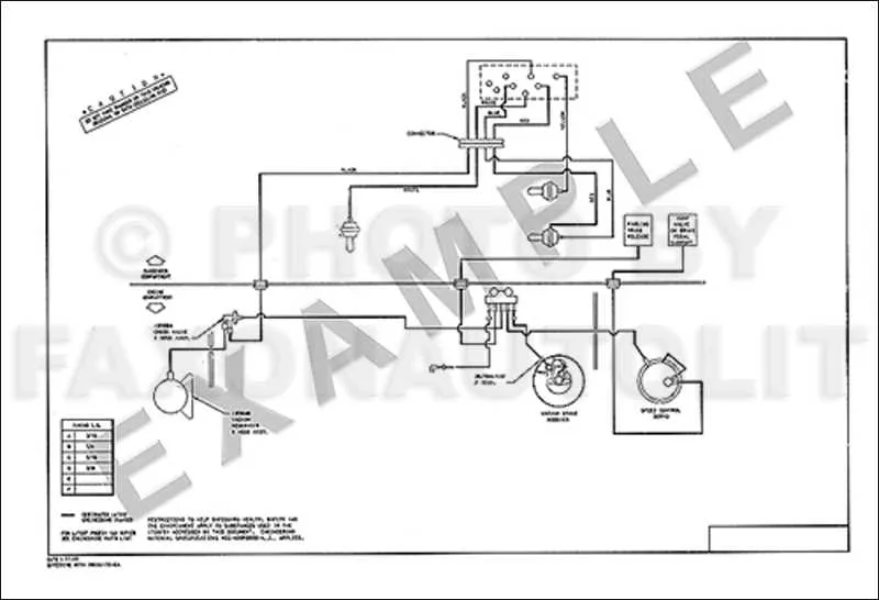
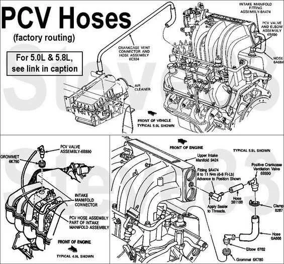
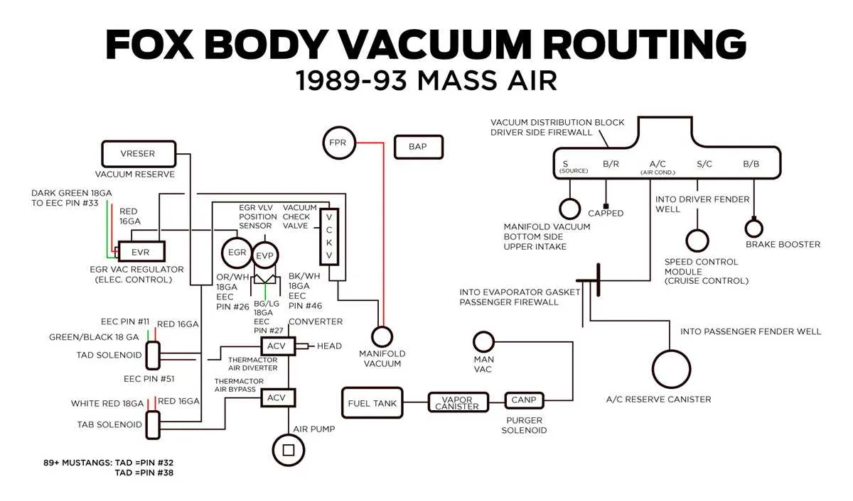
For optimal performance of the 5.0L V8 system, ensure that all hoses are connected correctly according to their respective ports. The primary vacuum source is typically located on the intake manifold, leading to various components such as the brake booster, emission control, and distributor advance. It’s crucial to check the integrity of all vacuum lines to prevent leaks that can affect the overall function of the components.
Start by routing the main line to the brake booster. From there, secondary lines should be routed to the distributor and various sensors such as the EGR (Exhaust Gas Recirculation) valve. Make sure to connect the small diameter lines to the carburetor or throttle body for correct operation of the air-fuel mixture controls. Each component should have its own dedicated line to avoid interference with other systems.
If any line becomes cracked or damaged, replace it immediately. Failing to do so can lead to poor engine performance, including rough idling or reduced power. Ensure that all connections are tight and free of any blockages. Testing with a vacuum gauge can help identify any discrepancies in the system.
Periodically inspect the hoses for wear and tear, especially those near heat sources. Use quality replacement parts that match the specifications outlined in the service manual. A properly maintained setup will ensure smooth operation and prolong the life of the system.
How to Read the Vacuum System Layout

Start by identifying the key components of the system, such as the intake manifold, hoses, and various sensors or actuators. These are the parts that rely on air pressure to operate correctly, and understanding their placement is essential for troubleshooting.
Look for the main hose connection points, often near the intake, which supply air pressure to various control systems. From there, trace the lines to individual components like the distributor advance, EGR valve, or brake booster. These lines must be free of cracks or blockages to maintain proper function.
Ensure you understand the flow of air: If the diagram shows a hose leading to the distributor, it means it controls timing based on pressure changes. Similarly, a hose connected to the brake booster controls power braking, which is critical for smooth driving.
Pay attention to the color coding or labeling: Different lines might be marked or colored differently for easy identification. This is crucial when making repairs or replacements, as using the wrong line can cause malfunctions.
Remember to check each connection carefully: Ensure all hoses are tightly sealed. Any air leak could affect the overall system’s performance and lead to poor engine performance or fuel inefficiency.
Lastly, always refer to a reliable source when in doubt. The configuration of the system can vary depending on the specific model or version, so double-checking with an accurate reference will save time and effort in diagnostics.
Common Issues with Vacuum Lines in V8 Systems

Ensure all rubber hoses are securely attached and free from cracks. This prevents leaks and inconsistent performance.
- Cracked or hardened hoses: Over time, rubber degrades, leading to air leaks. Inspect all hoses regularly for visible damage or brittleness. Replace any compromised lines.
- Poor connections: Even slight looseness in connections can cause leaks, affecting idle and throttle response. Use hose clamps to secure each connection.
- Clogged check valves: A blocked valve can disrupt proper air flow, leading to rough idling or stalling. Clean or replace the valve as needed.
- Faulty hoses in the emissions system: A leak here can trigger check engine lights and poor fuel efficiency. Check for damaged components and replace them promptly.
When diagnosing leaks, always start by visually inspecting the hoses. If no visible damage is found, consider using a smoke machine to pinpoint hidden leaks in the system.
Step-by-Step Guide to Fixing Air Leaks in a 5.0L V8

Start by identifying potential leak points such as hoses, intake manifold, or throttle body connections. Inspect all rubber components for cracks or degradation, as they are often the primary culprits.
Use a carburetor cleaner or brake cleaner around suspect areas while the engine is running. A change in engine speed indicates where the leak is located.
Once you locate the leak, remove the faulty component. If it’s a hose, replace it with a new one of the correct size and material. If it’s a gasket, make sure to clean both mating surfaces thoroughly before installing the new one.
Check the tightness of all bolts, especially around the intake manifold and throttle body. Over time, these bolts can loosen, leading to air infiltration. Tighten them to the manufacturer’s specified torque setting.
If the leak is within the intake manifold itself, it might be necessary to replace the entire manifold or use a sealing compound designed for high-heat applications to seal minor cracks.
After repairs, start the engine and monitor the idle speed. It should remain stable without fluctuations. If problems persist, repeat the diagnostic process and check for additional issues such as faulty sensors or poor electrical connections that could be contributing to the problem.