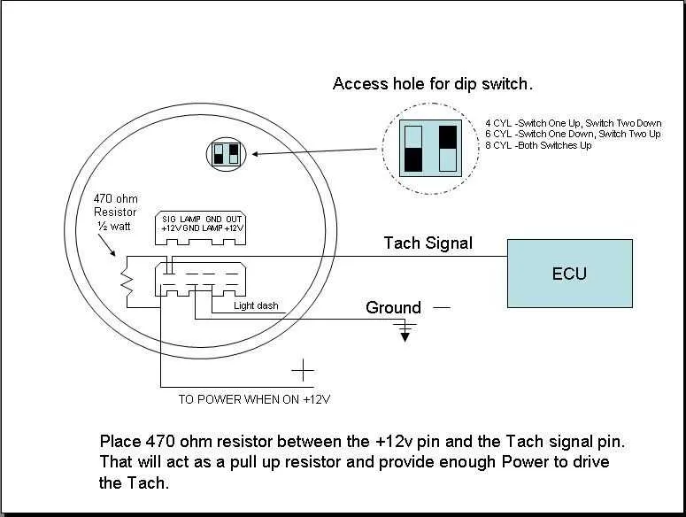
For optimal engine performance tracking, ensuring your RPM meter is correctly installed is crucial. Begin by connecting the power input to a reliable 12V source from your vehicle’s fuse box or ignition switch. This will provide the necessary power for the gauge to function consistently.
Grounding is a key element for accurate readings. Connect the ground wire securely to the vehicle’s chassis or a metal surface. A weak or inconsistent ground connection can lead to fluctuating or incorrect data on your display.
The signal input should be routed from the engine’s ignition system. Most systems will allow direct connection to the coil’s negative terminal or a dedicated tachometer output from the ECU. Ensure the signal wire is well-insulated and kept away from high-voltage lines to avoid interference.
After installation, calibrate the unit according to the engine’s specifications. This step is essential to ensure the readings match the engine’s true RPM levels. Many modern units have built-in calibration settings for ease of use. If yours does not, manual adjustment based on engine performance testing may be required.
Finally, verify the installation by testing the system under normal operating conditions. Ensure the readings are stable and match your engine’s performance. A properly installed and calibrated RPM meter will provide reliable data, helping you monitor and optimize your engine’s efficiency during all driving conditions.
Installation Guide for Performance Gauge Setup
For accurate RPM readings, connect the signal wire directly to the ignition system’s tachometer output. Ensure the ground connection is firmly attached to the vehicle chassis to avoid erratic readings.
Power the unit through a 12V source, typically the fuse box or a dedicated circuit. Double-check that the power line is fused to prevent potential damage.
Use the calibration screw on the back of the instrument to fine-tune the gauge if necessary. This is crucial for ensuring the display reflects accurate RPM values.
If the setup includes additional sensors, verify that each is connected according to the manufacturer’s specifications, especially when working with multi-channel systems. Any misconnection may result in incorrect data or system malfunctions.
Tip: Always test the setup before final installation. Start the engine and verify that the RPM reading corresponds to the actual engine speed by using a handheld tachometer for comparison.
Choosing the Right Components for Accurate RPM Monitoring Setup
To ensure proper installation and performance, select high-quality, reliable components. Focus on compatibility with your vehicle’s electrical system and the sensor’s precision. Here are key recommendations:
- Voltage Regulator: Ensure it is rated for your system’s voltage (usually 12V for automotive use). A stable voltage ensures accurate readings and prevents malfunction.
- Signal Resistor: Use a resistor rated for the correct ohm level to protect sensitive components and reduce noise interference.
- Grounding Wire: A dedicated, low-resistance grounding connection minimizes electrical noise, which can distort readings. Ensure it is securely fastened to a clean, bare metal surface.
- Power Lead: Use a thick gauge power cable (12-14 AWG) for the power connection to avoid voltage drop and ensure reliability.
- Connector Plugs: Choose weather-resistant, corrosion-proof connectors for durability. Consider sealed types to prevent moisture ingress.
Verify that all components are rated for automotive conditions, including temperature extremes and vibration. Testing the installation before finalizing the setup will help ensure stable operation.
Step-by-Step Guide to Connecting the RPM Gauge to Your Vehicle
Begin by ensuring your vehicle’s ignition is turned off before starting the installation. The first step is to locate the positive power source, which is typically found at the fuse box or the vehicle’s ignition switch. Use a 12V positive connection for a stable power supply.
Next, find a suitable ground point. This can be a clean, unpainted metal surface on the vehicle’s chassis. A good ground will ensure accurate signal transmission.
For the signal input, identify the vehicle’s coil or ECU wire that outputs the RPM data. For older systems, this may be the negative terminal on the ignition coil, while newer vehicles often send data via the ECU. Consult your vehicle’s manual for the correct wire if unsure.
Once the power and ground are connected, link the signal wire from the gauge to the RPM signal source. Ensure the connection is firm and secure to prevent any interruptions in the data feed.
If your setup requires illumination, connect the backlight wire to a switched power source that turns on when the vehicle’s lights are activated. This wire is typically found near the dashboard lighting circuit.
Before finalizing the installation, double-check all connections for accuracy. Test the unit by turning on the vehicle’s ignition to verify the gauge is receiving the proper signals and is functioning correctly.
After confirming functionality, secure the device in place using the mounting hardware provided. Ensure the display is positioned for easy viewing while driving.
Troubleshooting Common Issues with Performance Meters
Ensure the sensor is properly connected to the ignition system. A loose or corroded connection can result in erratic readings or complete failure. Tighten all connections and check for signs of wear on the cable.
If the needle fluctuates or reads inaccurately, inspect the ground connection. A poor ground can cause unstable or incorrect readings. Re-establish the ground to the engine block or another clean, solid point.
For non-responsive displays, check the power supply. Verify that the power wire is securely connected and that voltage levels are stable. A drop in voltage may cause the meter to malfunction.
If the unit shows no movement at all, test the signal wire leading from the ignition coil or distributor. Ensure the wire is intact, free of damage, and properly inserted into the meter’s signal input terminal.
In cases of flickering or jumping readings, check for electromagnetic interference. Keep wires away from high-voltage components like spark plugs and alternators. Using shielded cables can help mitigate interference.
Finally, if you’re using a unit with adjustable settings, ensure that the dip switches or settings for engine type and cylinder count are correctly configured. An incorrect setup can cause significant errors in display performance.