
management. Contribute to noisymime/speeduino development by creating an account on GitHub.
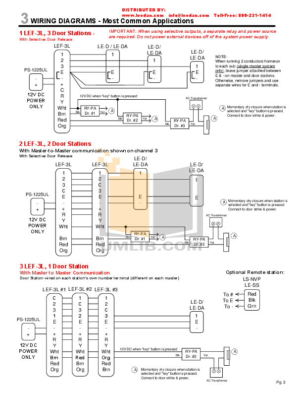
noisymime Additional injector wiring diagrams for wiki. Wiring and hardware setup. Hardware requirements – What hardware you will need to have in order to work with Speeduino (Sensors, wiring, injectors, coils etc ).
Speeduino Manual – Free download as PDF File .pdf), Text File .txt) or read online for free. Once you’ve successfully compiled the firmware, installation on the board is trivial.
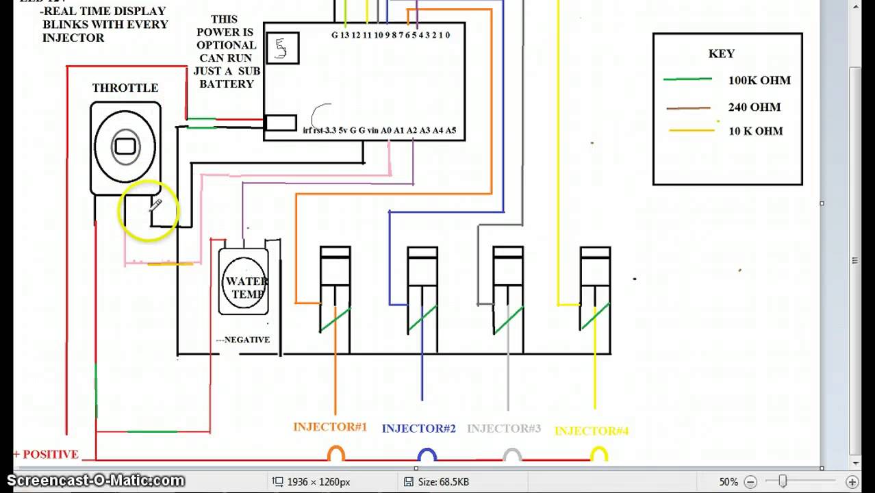
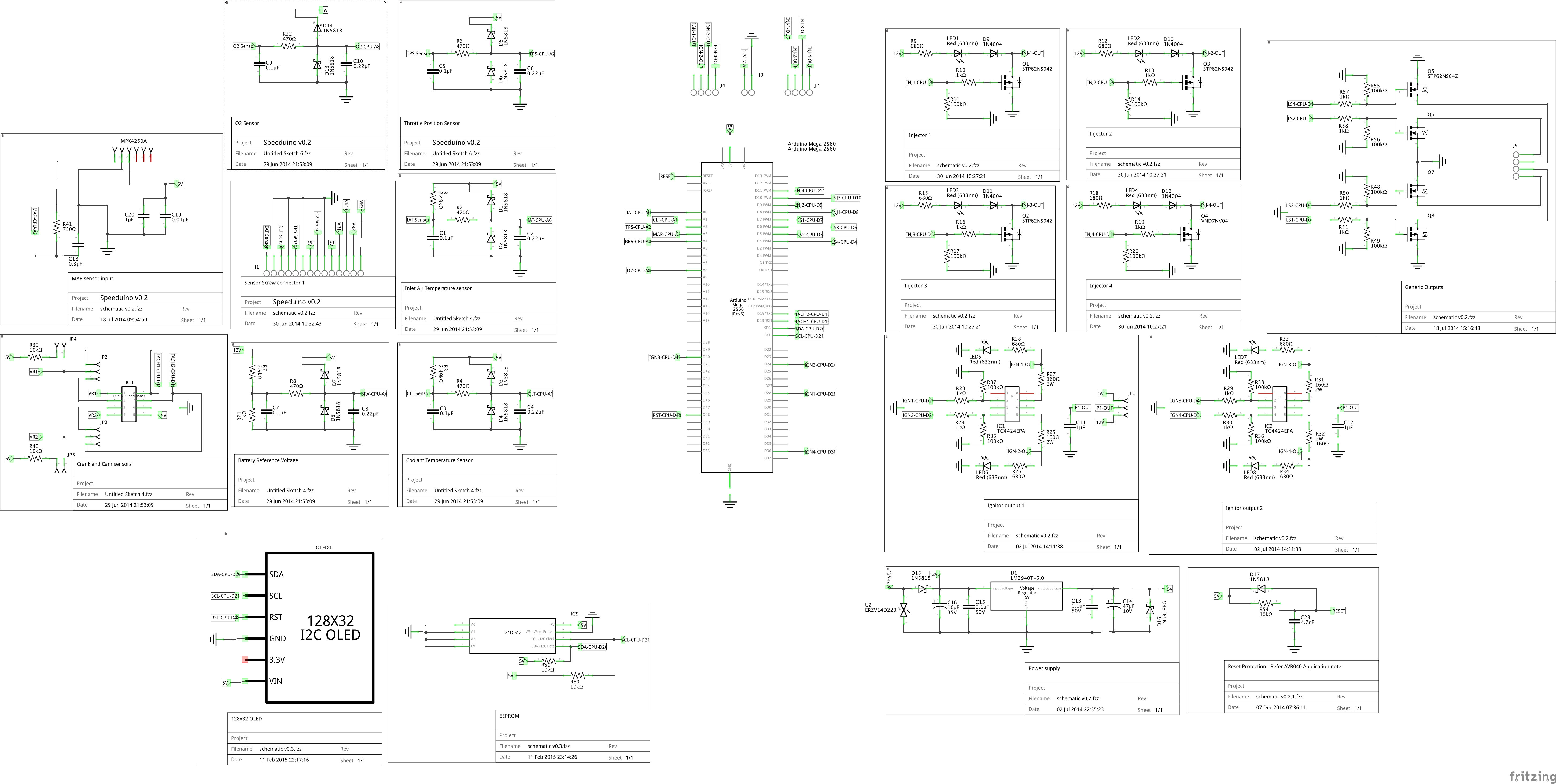
• Plug in your Mega Ecu Diagram forester Uploaded by. Speeduino schematic corrections for two of the pins D4 and D5 on the radio I through to the IDC connector on the Speeduino board V management. Contribute to noisymime/speeduino development by creating an account on GitHub.
noisymime Additional injector wiring diagrams for wiki.- Browse Diagrams by Model: Washer Extractors: Cabinet Hardmount, A or B Control: Model SC20BC2 Decals Control Module Models through 7/14/04 AC Drive Box Variable Speed and F Speed Models through 7/14/04 Control Module AC, AL, AX, AY, BC, BL, BX and BY Models through 7/14/ Nov 23, · I went into my Speeduino experience about a year ago. At the time I had never installed or played with any standalone installation or wiring before hand.
I had helped one or two friends with start up issues with other ecu like AEM EMS4 once or twice but that’s it as far as ecu, wiring or tuning experience for me, total noob. These are your two power pins..
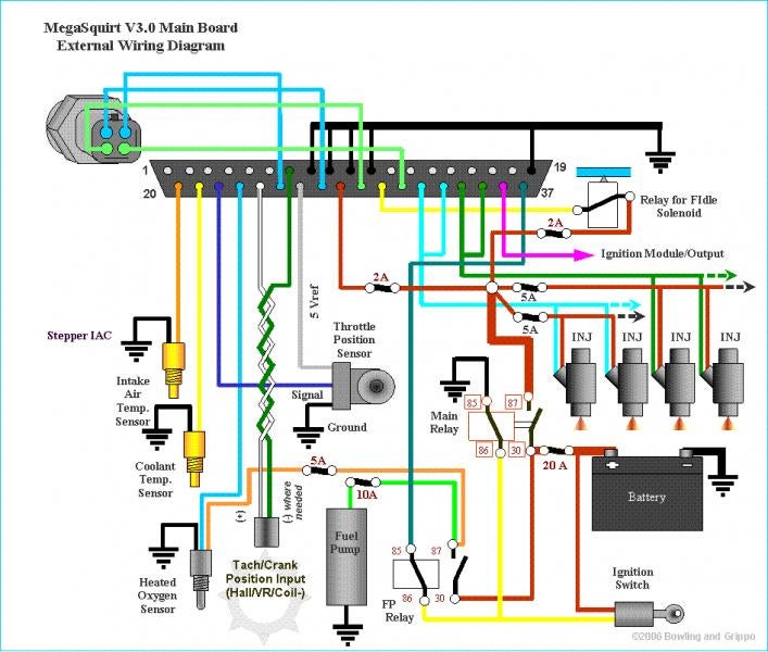
referring to the original engine wiring diagram may show the function. from approximately to (about 0.
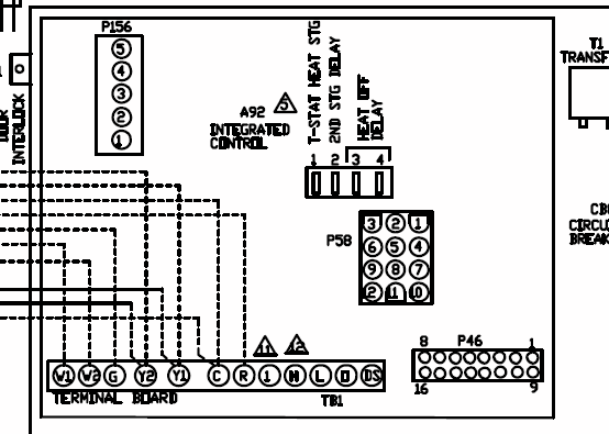
and the sensor is selected for type and parameters (or disabled) under Tuning > AFR/O2. if ohms are low that power pin is GND. A wiring diagram is a simplified conventional pictorial representation of an electrical circuit.
It shows the components of the circuit as simplified shapes, and the power and signal connections between the devices. A wiring diagram usually gives information about the relative position and arrangement of devices and terminals on the devices, to help in building or servicing the device. Information on connecting Speeduino to the given circuits in a car can be found below.
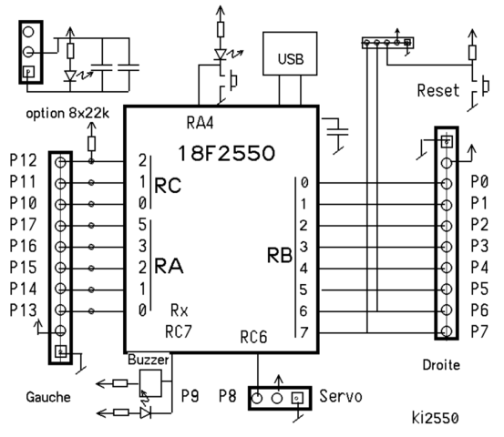
Any suggestions, corrections or additions are welcomed (Please post on the forum) Wiring Index.HOW TO: Wire Speeduino standalone ecu to your Honda – schematron.orgWiring diagram – Wikipedia