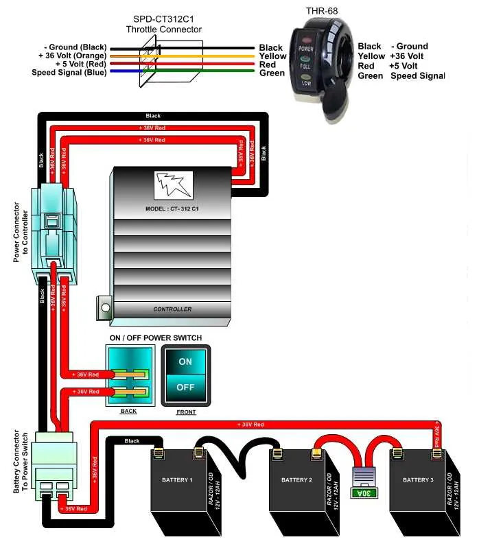
To ensure accurate functionality of your handlebar control unit, focus on the proper connection of each wire to its corresponding terminal. The primary components involved in the assembly are the actuator switch, power source, and control circuits. Begin by identifying the signal output from the device and trace it to the motor controller input.
Start by verifying voltage and resistance across the connections before installation. Ensure all terminals are clean and free of corrosion to maintain reliable conductivity. Pay attention to the polarity of the power supply, as reversed connections can lead to malfunction.
When connecting the control device to the system, opt for insulated connectors to minimize the risk of short circuits. Route the wires securely along the frame, avoiding any sharp bends or stress points that could compromise the wiring integrity. The system should be tested in stages after installation, checking the responsiveness and stability of the unit before finalizing the setup.
Wiring Setup for Hand-Controlled Speed Regulators

When connecting a hand-controlled speed regulator, it’s essential to ensure each wire is correctly routed for optimal performance. Follow these steps for a smooth installation:
- Identify the main connection points on your controller: typically, you’ll find three key terminals: power, ground, and signal.
- Connect the power wire from the controller to the positive terminal of the power source. Make sure the connection is secure to avoid any power disruptions.
- The ground wire should be linked to the vehicle’s main grounding point. This is crucial for the controller to function correctly.
- Finally, the signal wire needs to be connected to the controller input of the motor or electronic speed controller. This wire transmits the control signal for speed adjustments.
Ensure all connections are well-insulated and that there’s no chance of short circuits. It’s recommended to use heat shrink tubing to protect the wires from wear and exposure to the elements.
If your setup includes an external sensor or feedback mechanism, carefully route those wires along with the main signal wire, ensuring there are no sharp bends that could cause damage over time.
- For optimal performance, double-check that each connection is tight and free from corrosion.
- After installation, test the system by slowly increasing and decreasing speed, ensuring smooth operation without any interruptions.
Understanding the Pinout of the Control Switch
The control switch typically includes three main connections: power, ground, and signal. The power wire supplies the necessary voltage, usually 5V, which activates the switch. The ground wire completes the circuit, providing a return path for current flow. The signal wire transmits the varying voltage levels that correspond to the throttle position.
To ensure proper connection, verify the voltage output on the signal wire while adjusting the switch. The voltage should fluctuate as the position of the actuator changes. In most cases, the signal wire will output a range between 0 and 5V, with 0V corresponding to the lowest setting and 5V to the maximum setting. Incorrect connections or damaged wires can lead to faulty readings, affecting the system’s performance.
When troubleshooting, check the continuity of all connections using a multimeter. Ensure that the ground connection is stable and that the signal wire is free of interruptions. If the output does not vary as expected, inspect for possible short circuits or broken components in the wiring. Additionally, refer to the system’s documentation for specific pinout details, as some models may have slight variations in pin assignments.
Common Electrical Connection Problems and Fixes

Ensure proper insulation of all wires to prevent short circuits. Exposed or frayed wires often cause malfunction. Use electrical tape or heat shrink tubing to secure connections.
If the device is unresponsive, check for loose or corroded terminals. Tighten connections and clean the terminals using a contact cleaner to ensure optimal conductivity.
Inconsistent power or stuttering performance may result from poor grounding. Verify that the ground wire is securely attached to a clean, metal surface to prevent electrical noise interference.
Incorrect voltage output can occur due to faulty components. Test with a multimeter to confirm voltage is within the recommended range, and replace any damaged parts accordingly.
Check for any breaks in the circuit by inspecting the connectors and switches. Use a continuity tester to identify interruptions in the current path and replace any faulty connectors.
Step-by-Step Installation Guide for Handlebar Controller
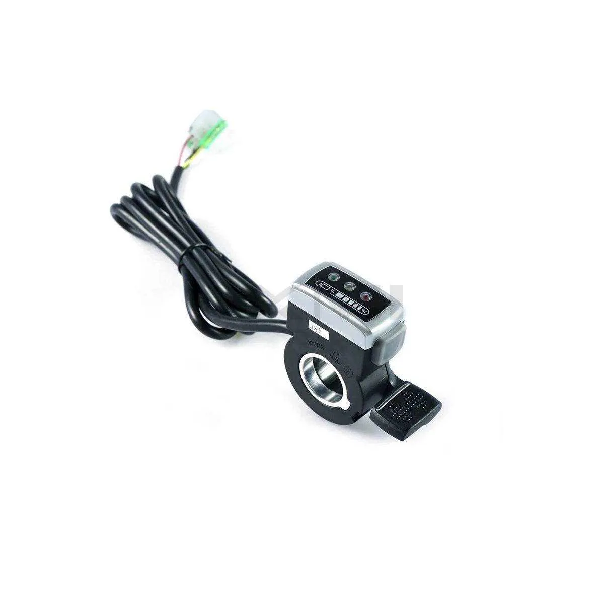
Begin by securing your vehicle or bike on a stable surface to ensure safety. Disconnect the battery to avoid any electrical hazards. Identify the correct mounting area on the handlebar where the controller will be installed. Typically, this is on the right-hand side for easy access. Ensure the mounting position allows for smooth operation of the device without obstructing other components.
Next, prepare the mounting bracket or the fixture that holds the controller. If necessary, adjust it according to the handlebar’s diameter. Use screws or clamps to securely fasten the bracket. Ensure the fixture is tightened but not overtightened to avoid damaging the components.
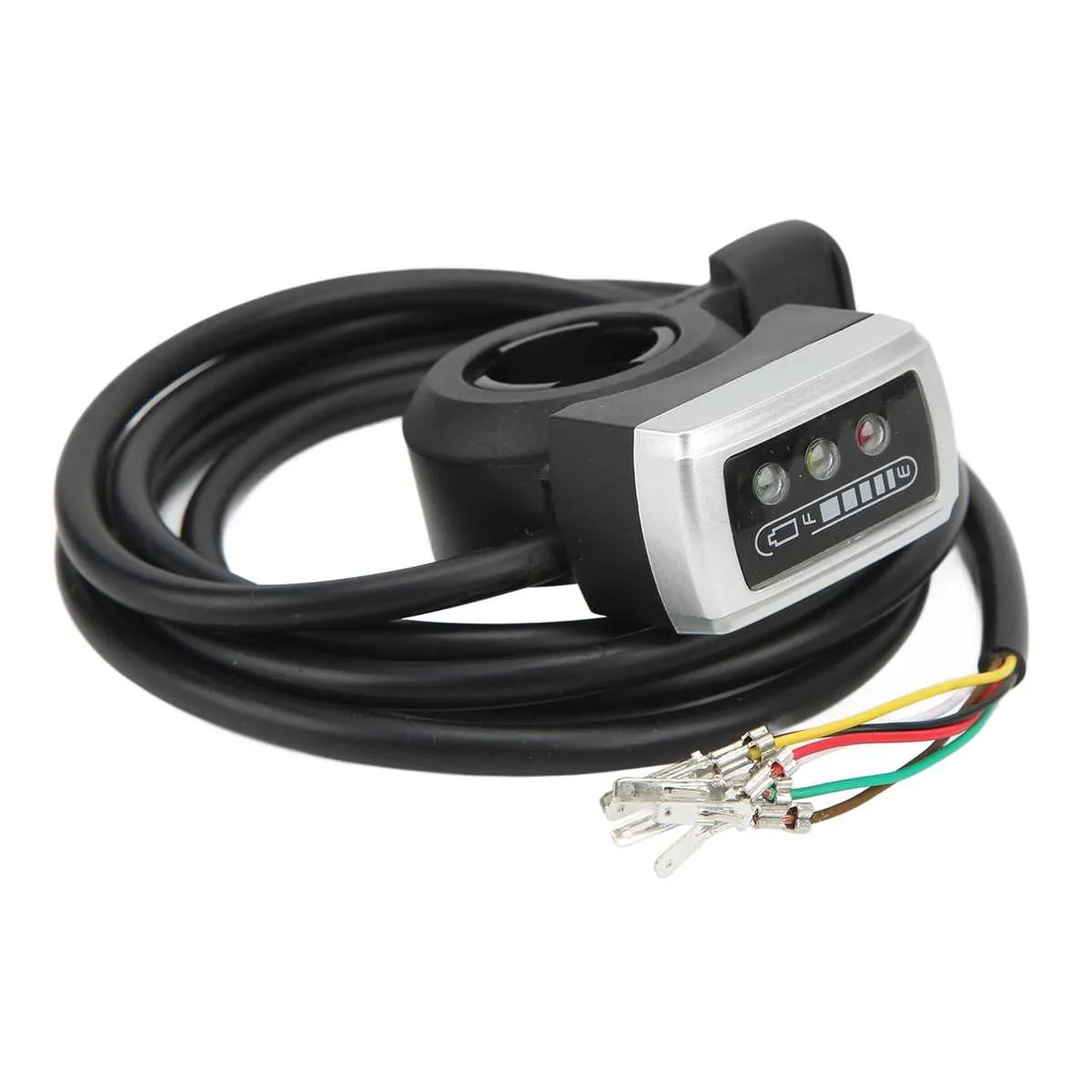
After the controller is mounted, locate the connecting cables from the controller unit. Attach the wiring to the appropriate power and signal connections. Match the colors or labeling provided with the device’s manual for correct installation. It is crucial that you connect the wires properly to prevent malfunctioning.
Once the wiring is secure, check the alignment of the control mechanism to ensure it can be operated comfortably. Adjust the handle position if necessary to ensure ergonomic handling while riding.
Before completing the installation, recheck all connections for any loose wires or potential short circuits. Once satisfied, reconnect the battery and test the functionality of the installed unit. Perform a slow and careful trial run to ensure the controller responds accurately to input and operates smoothly without any hindrances.
Finally, once testing is complete, tidy up the wiring by using zip ties or clamps to keep everything in place. Ensure that no wires are exposed or at risk of tangling with moving parts. Your handlebar controller is now ready for use.