For a reliable and efficient wiring of a two-position actuator, ensure to use a clear layout that accounts for all terminals involved. Start by identifying the terminals: one for the input, one for the output, and an additional terminal for grounding, if needed. Make sure the power supply is connected to the input terminal, while the output should lead to the device you intend to control.
Use quality cables that are rated for the power load to avoid voltage drops. The grounding terminal should be securely attached to a grounded point to prevent electrical hazards. The key to a stable and safe operation lies in proper isolation of the actuating mechanism, making sure that no short circuits can occur under any condition.
Next, for devices requiring a momentary signal, consider adding a protective component like a diode to shield against back-emf. This helps in prolonging the lifespan of the control mechanism. Double-check the polarity of the terminals, especially if you’re dealing with a DC-powered system. Incorrect wiring can lead to malfunction or even damage to the controlled device.
Once the setup is completed, test the circuit by toggling the mechanism through its operational range. This will allow you to verify if everything is working as intended, and if the device responds to changes in the state correctly.
Wiring Overview for a 2-Position Selector

To wire a 2-position selector, start by connecting the central terminal to the power source or common ground, depending on the application. The two outer terminals should be connected to the respective circuits that need to be activated or deactivated. Ensure that the wiring is secure and that there are no loose connections, as this can cause intermittent operation.
Important: When working with a mechanical actuator, the middle terminal is typically the common terminal, while the two others correspond to the switched positions. Be mindful of the contact rating to avoid overloading the device. Double-check for polarity when wiring DC circuits to avoid short circuits or damage to components.
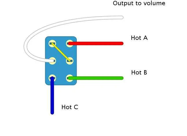
For applications requiring more than two positions, consider using a multi-position variant, where each additional terminal corresponds to a unique function. In such cases, ensure each position is clearly marked and wire according to the desired functionality of the system.
Tip: It’s advisable to use a continuity tester after wiring to ensure the proper activation of each position and that the circuit behaves as expected under load.
Wiring for SPDT Mechanism
To correctly wire an SPDT (Single Pole Double Throw) mechanism, follow these steps:
- Connect the common terminal (C) to the power supply or signal source.
- Attach one of the two secondary terminals (T1 or T2) to the first output device.
- Connect the second secondary terminal (T1 or T2) to the alternative output device.
- Ensure that the contacts between the common and secondary terminals are secure to prevent short circuits.
For a practical application, when the actuator is engaged, it will make contact with either T1 or T2, routing the current to the corresponding output device. This can be used for controlling two devices with one input point.
- If you need to reverse polarity, consider using a diode or relay to control the direction of current flow between the terminals.
- Ensure the components being controlled are compatible with the switching mechanism’s voltage and current ratings to avoid overload.
How to Connect a DPDT Toggle for Reversing Polarity
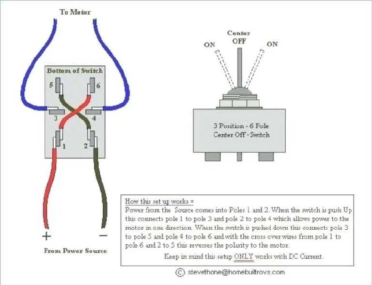
To reverse polarity using a DPDT mechanism, connect the device in the following way:
1. Identify the six terminals of the DPDT. Two are for the power input, and the remaining four are for the output direction change. The middle terminals are the common ones, while the outer ones determine the polarity.
2. Connect the positive (+) wire from the power source to one of the central pins. Do the same for the negative (-) wire on the opposite middle terminal.
3. Attach the positive output to one of the outer pins on the left side and the negative output to the opposite outer pin on the same side.
4. For the right side, swap the outputs. The positive output connects to the opposite left terminal, while the negative output connects to the opposite right one.
5. Once wired, toggling the device will change the polarity of the output–flipping between positive and negative connections on the output terminals.
Ensure all connections are secure to avoid electrical issues. Check the alignment and functionality before full application.
Common Errors in Wiring and How to Avoid Them

Incorrect Wiring of Terminals: Always ensure that the terminals are properly aligned with the intended circuit flow. Mistaking the input terminal for the output can cause malfunction. Double-check the terminal labels before securing the wires.
Using Incorrect Gauge of Wire: Insufficient wire thickness can lead to overheating and potential failure. Always match the wire gauge to the amperage requirements of your setup. Refer to the manufacturer’s specifications for guidance.
Failure to Properly Ground: Grounding provides safety and prevents electrical shorts. Ensure that the grounding wire is securely connected to the designated terminal and check for any loose or exposed connections that could create hazards.
Overloading the Circuit: Ensure that the current drawn by the device does not exceed the rated capacity of the component. Exceeding the limit can cause overheating or even permanent damage to the system. Verify the device specifications and compare them to the wiring ratings.
Not Securing the Wires Properly: Wires that are not securely fastened can cause intermittent connections or even electrical arcing. Make sure to properly clamp and insulate all exposed wires to avoid these issues.
Ignoring Polarity: Some components are sensitive to polarity. Reversing positive and negative connections can cause malfunction or damage. Always pay attention to the polarity indicators, especially for polarized devices.
Using Low-Quality Components: Cheap or substandard components may not handle the required load. Always use high-quality parts from reputable manufacturers to ensure longevity and proper functionality of the system.
Incorrect Orientation of Mechanisms: Ensure that the mechanism is oriented according to the manufacturer’s recommendation. Misalignment can result in improper operation or mechanical wear over time.
Not Testing Before Finalizing: Test the circuit thoroughly before finalizing the setup. Verify each connection, check for continuity, and confirm that all components function as expected under load to prevent issues later.