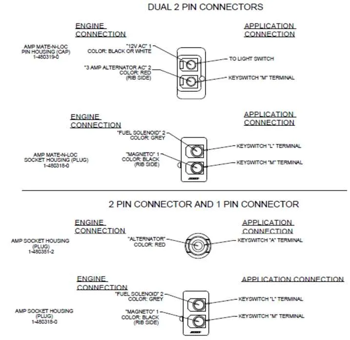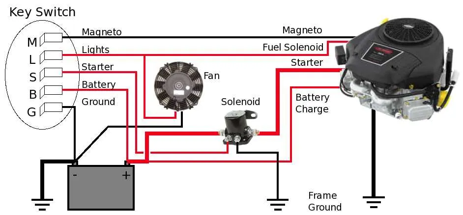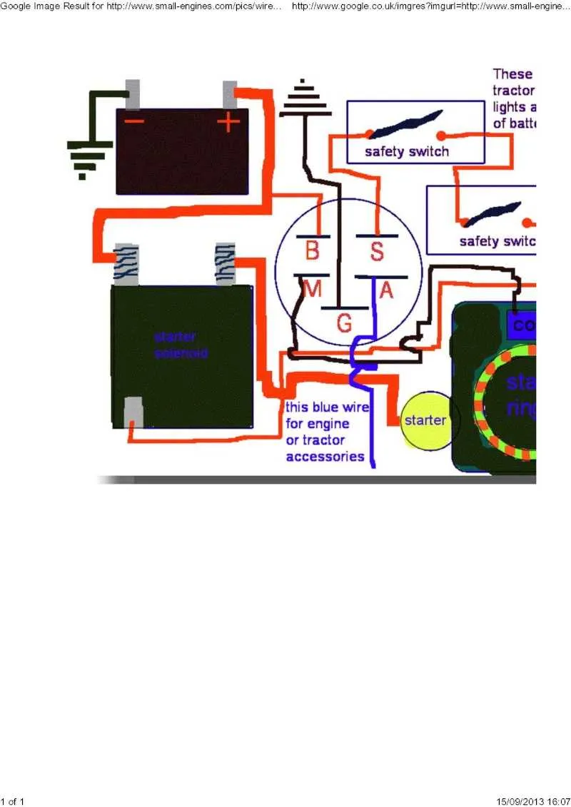
If you’re troubleshooting or replacing the control mechanism on a small engine, ensure you correctly identify and connect the six terminals on the electrical component that activates the start-up process. Each terminal plays a distinct role in powering the engine system, and improper connections can lead to malfunction or failure to start. Start by referring to the manufacturer’s specific terminal map to ensure compatibility with your model.
Terminal 1 typically connects to the battery, providing power to the component. This terminal is crucial as it initiates the flow of electricity once the control mechanism is engaged. Make sure the connection is secure and free from corrosion.
Terminal 2 is often used for the ground connection. It completes the circuit, allowing the current to flow back safely. A solid ground is essential to avoid short circuits or potential electrical fires.
Terminal 3 connects to the starter motor, directly controlling its operation. Ensure this wire is properly insulated and not exposed to prevent accidental shorting while in operation. A weak or damaged connection here can prevent the engine from turning over.
Terminal 4 is usually dedicated to the safety or kill switch, cutting off power to the engine when disengaged. Check the switch’s condition regularly to avoid unexpected engine shutdowns.
Terminals 5 and 6 are typically used for auxiliary features, such as lights or additional circuits, depending on the engine’s configuration. Double-check these connections, especially if your equipment includes extra components that need to be powered when the engine is running.
6-Terminal Engine Control System Wiring Guide
When wiring a 6-terminal engine control component, start by identifying the main connections for the battery, start, and grounding system. The terminals are typically numbered to simplify installation, with each point serving a specific function. The first terminal should be connected to the positive battery terminal, ensuring proper power supply.
The second terminal is responsible for the starter motor connection, activating the engine. This connection is usually linked to the solenoid that triggers the ignition when the system is engaged. The third terminal is for the ground, establishing a secure return path to the battery. Ensuring a strong ground is critical to prevent electrical malfunctions.
The fourth terminal is used to control safety mechanisms such as the seat or brake interlock, preventing the engine from running under unsafe conditions. The fifth terminal is commonly tied to a charging system or alternator, ensuring the battery maintains sufficient charge during use.
The sixth terminal connects to the fuel system, managing the flow based on engine requirements. Proper wiring of this terminal guarantees the fuel pump operates correctly, ensuring smooth engine performance.
Accurate connections and a strong understanding of the system will prevent malfunctions and prolong the lifespan of your engine. Always consult the manufacturer’s manual for specific wiring instructions for your engine model.
Understanding the Pinout of a 6-Pin Starter Control

When dealing with a 6-pin starter control module, it is essential to know the specific functions assigned to each terminal. This knowledge ensures proper connection and avoids damaging the system. Below is a breakdown of each terminal’s function:
Pin 1 is typically connected to the battery’s positive terminal. This serves as the primary power source, feeding the necessary voltage to the control system.
Pin 2 is often designated for the starter solenoid. This pin sends the current required to engage the starter motor, facilitating the engine’s cranking process.
Pin 3 is commonly used for the safety switch. It connects to the safety mechanism, ensuring that the system will not operate unless all safety conditions are met.
Pin 4 is linked to the ground. It provides the return path for the electrical flow, ensuring the circuit functions properly.
Pin 5 usually serves as the connection to the ignition coil. This is crucial for initiating the spark needed for engine combustion once the system is powered on.
Pin 6 often connects to the lighting or accessory circuit. This pin powers additional components such as headlights or other electrical accessories that may be part of the system.
Always consult the manual of the specific model for exact pinout assignments, as some variations may exist. Ensuring the correct connections between these terminals is key to reliable system performance.
Step-by-Step Guide to Connecting the 6-Terminal Starter Control

Start by disconnecting the power source to avoid accidental shocks. Ensure the battery is removed or disconnected before proceeding with the connection process.
Identify the terminals on the starter control. The most common setup for a six-terminal device includes connections for the battery, ground, starter motor, and auxiliary components such as the safety switch or alternator.
Attach the first terminal to the battery’s positive post. This terminal is typically linked to the power source, so it’s crucial to ensure a firm connection.
Next, connect the ground terminal to the metal frame or chassis. This is important for completing the circuit and preventing electrical faults. It ensures all components are safely grounded.
The third terminal connects directly to the starter motor. This link allows the starter motor to receive power when the system is activated. Be sure this connection is tight to avoid starting issues.
For the fourth terminal, connect it to the safety switch. This connection is essential for the system to only engage when the safety conditions are met, such as the brake being applied or the blade being disengaged.
Attach the fifth terminal to the alternator if applicable. This is for recharging the battery during operation. Check the alternator’s voltage output to ensure it matches the required specifications for your model.
The sixth terminal is generally used for auxiliary features such as lights or other optional components. Ensure the wire connected to this terminal is adequately insulated and secured to avoid short circuits.
After all terminals are connected, double-check each one for tightness and security. Loose connections can lead to malfunction or damage. Once everything is confirmed, reconnect the battery and test the system to ensure proper functionality.
Common Wiring Issues and Troubleshooting for 6-Terminal Key Units
Check for loose or corroded connections first. Over time, terminals can become unreliable due to wear, causing the system to fail intermittently.
- Loose Connections: Ensure all cables are securely attached to the terminals. Tighten screws and nuts, but avoid over-tightening to prevent damage to the contacts.
- Corrosion: Inspect each terminal for signs of rust or dirt buildup. Clean any affected areas with a wire brush or contact cleaner to restore conductivity.
- Broken or Damaged Wires: If wires are frayed, cracked, or broken, replace them immediately. Continuity should be checked with a multimeter to verify proper operation.
Next, test for faulty components. A malfunctioning component can disrupt the power flow, making the unit unreliable or inoperative.
- Failed Relay: If the system fails to activate, the relay might be defective. Test it with a multimeter to ensure it’s functioning correctly.
- Burnt Terminals: Overloaded circuits or short circuits can cause terminals to burn. Replace any charred terminals and inspect the circuit for underlying issues.
If the problem persists, check for a malfunction in the control circuit. A poor connection between the key terminal and the control module can prevent proper activation.
- Control Module Issues: Inspect the connections leading to the control module. Ensure they are clean and securely attached.
- Signal Interference: Ensure that no external devices are causing electrical noise that may affect the circuit’s function.
Lastly, consider environmental factors. Moisture or extreme temperatures can cause short circuits or interruptions in signal transmission.
- Moisture: In humid environments, protect all connections with waterproof covers or sealants to prevent water damage.
- Extreme Heat: High temperatures may weaken plastic connectors. Replace worn connectors or relocate components away from excessive heat sources.