
In the world of software development, Unified Modeling Language (UML) diagrams play a crucial role in visually representing the structure, behavior, and relationships of a system. One of the most commonly used UML diagrams is the Component Diagram, which helps in understanding the software architecture by illustrating the various components and their interactions.
A component is a modular and independent unit of a system that encapsulates the implementation and exposes a set of interfaces. Component diagrams use a set of standardized symbols to represent different types of components and their relationships. These symbols provide a visual representation of the system’s architecture, making it easier for developers and stakeholders to understand and communicate about the system.
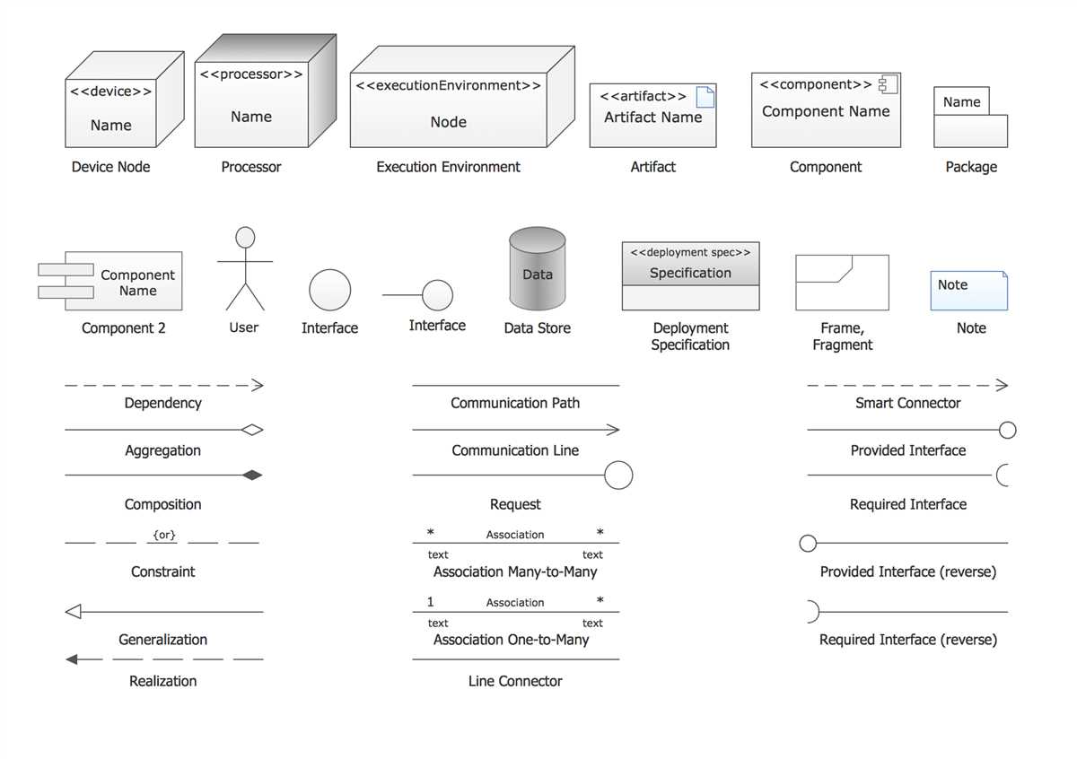
Some of the key symbols used in UML Component Diagrams include:
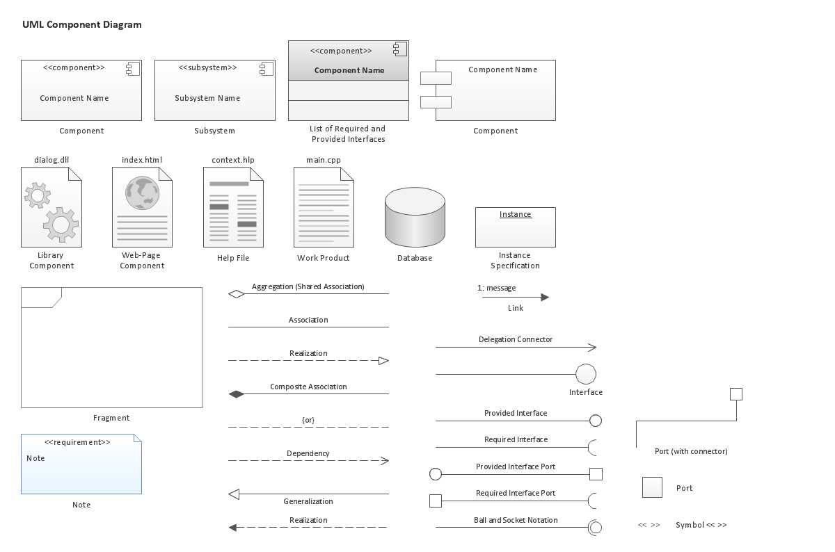
- Component: Represents a self-contained and replaceable part of a system. It is depicted as a rectangle with two tabs on the top.
- Interface: Defines a contract between the component and its environment. It is represented as a circle with the name of the interface inside.
- Dependency: Shows that one component depends on another. It is represented by a dashed arrow pointing from the dependent component to the component it depends on.
- Association: Represents a relationship between two components. It is illustrated by a solid line connecting the components.
- Generalization: Shows an inheritance relationship between two components, where one component is a specialized version of another. It is depicted by a solid line with a triangular arrowhead pointing to the general component.
Understanding these symbols is essential for effectively utilizing UML Component Diagrams as a tool for software development and system analysis. By visually representing the system’s architecture in a clear and concise manner, these diagrams help teams collaborate, identify potential issues, and design more robust and scalable software systems.
UML Component Diagram Symbols: A Comprehensive Guide
A UML component diagram, also known as a UML deployment diagram, is a visual representation of the different components and their relationships in a system or application. It is widely used in software engineering to analyze and design complex systems, aiding in the understanding and communication of the system’s architecture. In this comprehensive guide, we will explore the various symbols used in UML component diagrams and their meanings.
1. Component Symbol:
The component symbol is represented by a rectangle with two tabs on the top. It represents a modular, self-contained unit of a system, such as a software module, library, or hardware component. The name of the component is usually written inside the rectangle, along with its stereotype if applicable.
2. Interface Symbol:
The interface symbol is represented by a circle connected to a component symbol by a solid line. It represents an abstraction that defines a set of operations or services provided by a component. The name of the interface is usually written inside or next to the circle.
3. Dependency Symbol:
The dependency symbol is represented by a dashed arrow pointing from one component to another. It represents a dependency relationship between two components, where changes in one component may affect the other component. The arrow is annotated with the type of dependency, such as “uses,” “requires,” or “implements.”
4. Assembly Symbol:
The assembly symbol is represented by a solid line connecting two components, with a hollow diamond at the end of the line pointing towards the component being assembled. It represents a composition relationship, where the assembly component consists of the assembled component. The diamond is annotated with the multiplicity of the assembly relationship.
5. Provided Interface Symbol:
The provided interface symbol is represented by a solid line with an open arrow pointing from a component to an interface. It represents that the component provides or implements the operations or services defined by the interface. The arrow is annotated with the name of the interface and the type of interaction, such as “uses,” “extends,” or “implements.”
6. Required Interface Symbol:
The required interface symbol is represented by a solid line with an open arrow pointing from an interface to a component. It represents that the component requires or relies on the operations or services defined by the interface. The arrow is annotated with the name of the interface and the type of interaction, such as “uses,” “extends,” or “implements.”
By understanding and using these UML component diagram symbols, software engineers can effectively model and communicate complex system architectures. These symbols provide a standard visual language for representing the various components and their relationships within a system, enabling better design, analysis, and documentation.
What are UML Component Diagrams?
UML component diagrams are a type of structural diagram that represent the physical and logical components of a software system. They provide a visual representation of the system’s architecture, showing how different components interact with each other to achieve specific functionality.
These diagrams are commonly used in software development to help designers and developers understand the overall structure of a system and how different components fit together. They are especially useful when dealing with complex systems that have multiple layers or modules, as they allow for a clear and organized representation of the system’s components and their dependencies.
UML component diagrams use various symbols to represent different types of components and relationships between them. Some of the key symbols include:
- Component: Represents a modular and self-contained part of a system, such as a class, package, or module.
- Interface: Defines a contract for communication and interaction between different components.
- Dependency: Represents a relationship where one component depends on another for its functionality.
- Association: Represents a relationship between components that is not as strong as a dependency, but still has some form of connection.
- Generalization: Represents a relationship where one component is a specialized version of another component, inheriting its properties and behavior.
By using these symbols and relationships, UML component diagrams provide a clear and concise way to visualize a software system’s architecture and design. They help in understanding the system’s composition, dependencies, and overall structure, making it easier for developers to analyze and modify the system as needed.
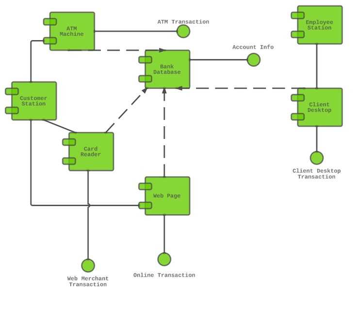
Use of UML Component Diagrams
UML Component Diagrams are a powerful tool for visualizing the structure and relationships of complex software systems. They provide a high-level overview of the components that make up a system and how they interact with each other. These diagrams are particularly useful for software architects and developers who need to understand the overall structure of a system and how its various components work together.
In UML Component Diagrams, components are represented as rectangles, with each component having its own name. The relationships between components are shown with lines and arrows, indicating dependencies, associations, and other connections. These diagrams can also include interfaces, ports, and connectors to represent the communication between components.
The main advantage of using UML Component Diagrams is that they provide a clear visual representation of the system’s structure, allowing stakeholders to easily understand the overall architecture. They can be used to identify dependencies between components, identify potential bottlenecks or performance issues, and facilitate communication between different teams working on the same system. Additionally, UML Component Diagrams can serve as a documentation tool, helping developers and maintenance teams to understand the system’s design and make modifications or improvements more efficiently.
Key elements in UML Component Diagrams include:
- Component: Represents a modular, self-contained piece of software or hardware.
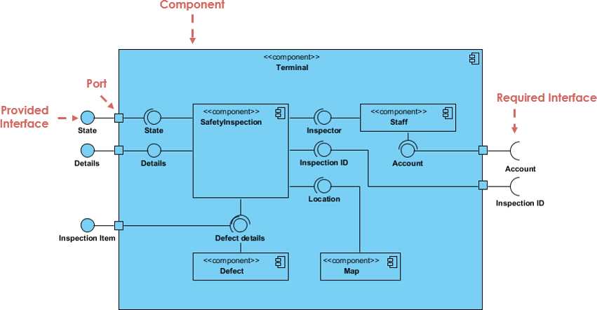
- Interface: Specifies contracts between components, defining the operations and attributes that they provide or require.
- Port: Represents a point of interaction between a component and its environment.
- Connector: Represents a communication link between components, often visualized as a line or arrow.
- Dependency: Indicates that one component depends on another component.
- Association: Represents a relationship between two components, typically showing that one component uses or contains another component.
Overall, UML Component Diagrams are an essential tool for understanding and documenting the structure of complex software systems. By providing a visual representation of the system’s components and their relationships, these diagrams can help stakeholders visualize the architecture and make informed decisions about the system’s design, maintenance, and evolution.
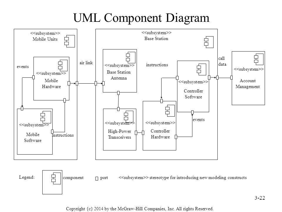
Overview of UML Component Diagram Symbols
In UML (Unified Modeling Language), a component diagram is used to represent the physical components of a system and their relationships. It provides a high-level view of how the different parts of a system interact and work together. Component diagrams are particularly useful for software engineers and developers to understand the structure and organization of a software system.
There are several symbols used in UML component diagrams to represent different elements of a system. These symbols help to visualize the components, interfaces, and relationships between them. Some of the key symbols include:
- Component: This symbol represents a modular and independent part of a system. It can be a class, a package, a file, or even a subsystem. Components are depicted as rectangles with compartments that show the name and other details.
- Interface: An interface defines the contract or the set of operations that a component provides. In UML component diagrams, interfaces are shown as a circle with the name of the interface written inside.
- Dependency: This symbol shows that one component depends on another component. It represents a relationship where a change in one component may affect another component. Dependencies are indicated by a dashed arrow pointing from the dependent component to the component it depends on.
- Association: Associations represent a relationship between two components. It indicates that the components are somehow connected or have a dependency. Associations are drawn as solid lines with optional arrowheads to indicate the direction of the relationship.
In addition to these symbols, UML component diagrams may also include other elements such as attributes, ports, connectors, and stereotypes to provide more details about the components and their relationships. By using these symbols effectively, software engineers can create clear and concise diagrams that can be used to analyze, design, and communicate the architecture of a system.
Component Symbol
A component symbol in UML component diagrams represents a self-contained and independent unit of software or hardware that has well-defined interfaces and can be replaced or upgraded without affecting other components. It is used to represent the physical or logical parts of a system, such as software modules, libraries, subsystems, or hardware devices.
The component symbol is typically represented as a rectangle with a smaller rectangle at the top, which represents the name of the component. Inside the main rectangle, the component can be divided into different parts, each representing a specific functionality or responsibility. These parts are connected by lines that represent the dependencies or interactions between them.
Components in UML component diagrams can be classified into two types: atomic components and composite components. Atomic components are indivisible and cannot be further decomposed, while composite components are composed of smaller sub-components. Composite components can be used to represent higher-level system structures, such as subsystems or modules.
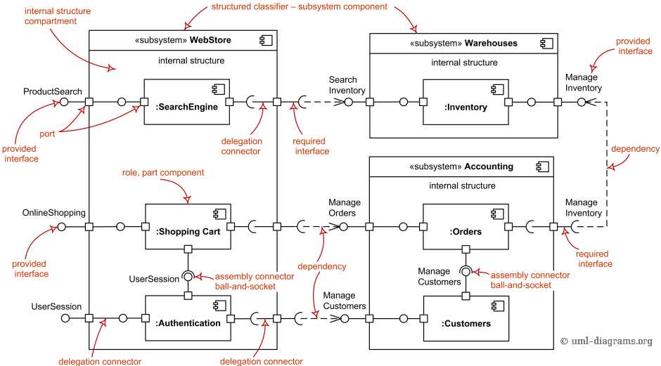
- Ports: Ports are used to represent the interfaces of a component. They act as endpoints through which the component can interact with other components or external systems. Ports can be shown as small squares or circles on the sides of the component symbol.
- Provided Interface: The provided interface represents the services or functionalities that a component offers to other components. It is depicted as a lollipop shape attached to the component’s port.
- Required Interface: The required interface represents the services or functionalities that a component depends on or requires from other components. It is depicted as a half-moon shape attached to the component’s port.
- Dependencies: Dependencies between components are shown as lines connecting the required interface of one component to the provided interface of another component. These lines indicate that one component depends on or requires the services of another component.
Overall, the component symbol in UML component diagrams provides a visual representation of the structure and interactions between different components in a system, allowing for better understanding and analysis of system architecture and dependencies.
Interface Symbol
An interface in UML component diagrams is represented by a circle with the name of the interface inside. The circle is connected to the component or class that realizes or implements the interface through a solid line. The circle symbolizes the contract or set of operations that the component or class implementing the interface must adhere to.
The interface symbol serves as a contract between the components or classes in a system. It defines a set of methods or operations that the implementing component or class must provide. The interface can have multiple operations, each represented by a method signature inside the circle. These operations define the behavior that can be expected from the component or class that implements the interface.
The interface symbol can be seen as a way to achieve abstraction and encapsulation in a system. It allows components or classes to interact with each other through well-defined interfaces, without knowing the internal implementation details. This promotes modularity and reusability, as components or classes can be easily replaced or extended as long as they adhere to the contract defined by the interface.
The interface symbol can also be used to represent provided and required interfaces in a system. Provided interfaces are the ones that a component or class implements and exposes to other components or classes, while required interfaces are the ones that a component or class depends on and needs to function properly. This distinction helps in understanding the dependencies between components or classes in a system.
Overall, the interface symbol in UML component diagrams is a powerful tool for designing and understanding the structure of a system. It allows for clear communication of the expected behavior between components or classes, promotes modularity and reusability, and helps in managing dependencies.
Package Symbol
A package symbol in UML component diagrams represents a group of related components and classes. It provides a way to organize the components and classes into logical units, making it easier to understand and manage the system’s structure.
The package symbol is represented as a rectangle divided into two compartments. The top compartment contains the package name, which should be descriptive and meaningful. The bottom compartment contains the components and classes contained within the package.
The package symbol can be used to represent different levels of abstraction. For example, it can represent a high-level package that contains several sub-packages, each representing a different subsystem or module of the system. It can also represent a low-level package that contains a group of closely related classes.
Furthermore, the package symbol can be used to show dependencies between packages. For example, an arrow can be used to indicate that one package depends on another. It can also be used to show the visibility of packages, with different symbols representing public, private, or protected packages.
In summary, the package symbol in UML component diagrams is a powerful tool for organizing and visualizing the structure of a system. It helps to create a clear and understandable representation of the system’s components and classes, making it easier to design, develop, and maintain the system.
Dependency Symbol
Dependency is a relationship between two components where one component depends on the functionality provided by the other component. It represents that the dependent component requires the services, interfaces, or operations provided by the supplier component.
A dependency is represented in a UML component diagram using a dashed arrow with an open arrowhead pointing from the dependent component to the supplier component. The arrow indicates the direction of the dependency, i.e., the dependent component relies on the supplier component for functionality.
Dependencies are commonly used to show the relationship between higher-level components and lower-level components. They help in understanding the structure and interactions within a system by showing how different components are interconnected.
Summary:
- Dependency represents a relationship where one component depends on the functionality provided by another component.
- It is represented by a dashed arrow with an open arrowhead.
- The arrow points from the dependent component to the supplier component.
- Dependencies help in understanding the structure and interactions within a system.