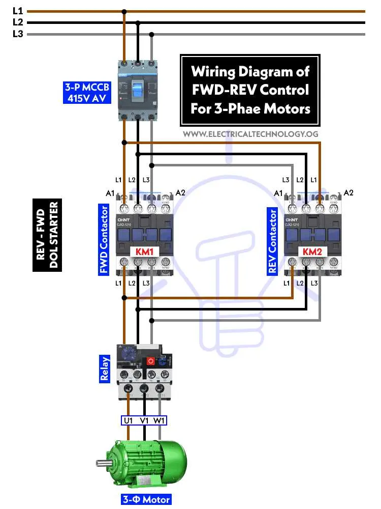
To properly configure a system that allows you to alternate the rotation direction of a high-voltage electric engine, ensure that you use a properly rated control component capable of managing dual-phase currents. Begin by selecting a component designed to handle the amperage and voltage of the device, ensuring compatibility with the 480V input supply.
Next, connect the leads from the two-phase power source to the primary input terminals of your control unit. After this, wire the two-phase lines to a set of control points that allow for the inversion of current flow, thus enabling reverse and forward motion of the apparatus. It is essential to ensure that the phase connections are secure to avoid electrical issues or hazards during operation.
For an added layer of protection, integrate a thermal overload protector in the control circuit to prevent excessive heat buildup that could damage components. Additionally, keep all wiring connections clean and insulated to reduce the risk of electrical shorts or inadvertent contact. Use a multimeter to verify the functionality of the setup after completion.
Test the system by activating the control point for forward and reverse operation. Ensure that the engine runs smoothly in both directions without any abnormal noise or vibration, which could indicate incorrect wiring or an imbalance in the circuit. Finally, confirm that all safety measures are in place, including proper grounding and insulation.
Wiring a Reversing Switch for 480V Motor Diagram
To successfully change the direction of a 480V unit, connect the necessary components with precision. Use a double-pole double-throw (DPDT) contactor to achieve polarity reversal. Ensure the terminals on the contactor are correctly labeled for input and output connections. The contactor’s common terminals should be attached to the power lines, while the output terminals link to the coil terminals.
Key consideration: When implementing a reversing setup, always ensure that the contactors are rated for high voltage and are compatible with the amperage of the equipment you’re controlling. Use properly sized circuit breakers to protect against overload and short-circuit risks.
For added protection, install thermal overload relays between the contactor and the load to avoid damage in the event of an overcurrent condition. Carefully arrange the line connections in such a way that the live wires alternate in the two poles, making sure to isolate the neutral line at all times.
Label all connections clearly to prevent any miswiring or accidental shorts. Implementing safety interlocks can further safeguard the system, ensuring that the direction cannot be changed while the unit is in operation, which could lead to electrical faults or mechanical damage.
Understanding the Basic Components of a Reversing Switch Circuit for 480V Motor

To control the direction of rotation in a 480V system, it is crucial to utilize two contactors and an auxiliary relay in combination with the control circuitry. The contactors play a primary role in connecting or disconnecting the high voltage supply to the device, while the auxiliary relay is responsible for controlling the direction of the current flow.
Contactor Configuration: Two contactors are typically arranged in a cross-pattern, each controlling the flow to opposite windings of the device. These contactors must be designed to handle the high voltage levels without risk of overheating or failure. Ensure that each contactor has a coil voltage rating that matches the control voltage, which is commonly 24V or 120V AC for this kind of system.
Auxiliary Relays: The auxiliary relays serve to shift the current direction by switching the connection between the windings. These relays are triggered by a control circuit, ensuring the current flows in the opposite direction when needed. Proper selection of relays with the appropriate amperage and voltage ratings is essential for reliable performance.
Overload Protection: A thermal overload relay should be included in the setup to protect the entire assembly from current spikes or sustained overcurrent. The thermal protection ensures that the system automatically disconnects if an excessive load is detected, preventing damage to components.
Control Circuit: The control circuit must be designed to activate the relays and contactors in the proper sequence to reverse the flow of electricity efficiently. Typically, push-button switches or toggle switches are used for manual control, though automated systems may incorporate sensors or timers.
Note: Ensuring proper grounding and using properly rated cables is critical for safety in any 480V system. Always adhere to local electrical codes and manufacturer specifications when designing or installing this configuration.
Step-by-Step Guide to Wiring a Reversing Switch for a 480V Motor

To reverse the rotation direction of an industrial power unit running on a 480V supply, follow these exact steps:
- Disconnect power before starting. Ensure the circuit is de-energized by cutting off the main electrical supply to avoid accidents.
- Prepare the contactors. You’ll need two contactors: one for forward rotation and one for reverse. Ensure they are rated for the voltage and current load.
- Connect the first contactor. Attach the input terminals from the power supply to the contactor’s L1 and L2 terminals. Connect the load terminals of the contactor to the motor’s line input wires.
- Set up the second contactor. Repeat the first step for the reverse contactor. The connections to the power supply will remain the same, but this contactor will handle the reversing operation.
- Cross-wire the two contactors. Connect the load terminals of the first contactor to the second contactor’s terminals. This crossover configuration allows for swapping the phase connections, thereby changing the direction of rotation.
- Install interlocking mechanisms. For safety, use mechanical or electrical interlocking between the contactors to prevent both from being energized simultaneously. This step is crucial to avoid damage or short-circuiting.
- Check the control circuitry. Wire the control buttons (start, stop, reverse) to control the respective contactors. Typically, a push button will energize the forward contactor, while another button will energize the reverse one.
- Verify connections. Double-check each connection for proper continuity, grounding, and insulation. Ensure all terminals are tightly secured to avoid any loose connections or electrical faults.
- Test the system. Power on the circuit and test the operation. Engage the forward and reverse control to ensure proper rotation change without any issues.
Remember to follow the local electrical codes and safety standards for installation and troubleshooting.
Common Troubleshooting Tips for Reversing Circuits on High Voltage Equipment
1. Ensure the control voltage is correct. If there’s no response when operating the control, check the circuit’s supply voltage against the specifications of the control components. Insufficient voltage can cause a malfunction.
2. Inspect the contactors for proper operation. A faulty or worn-out contactor can result in a circuit failure or inconsistent functionality. Check for signs of overheating or pitting on contacts, and replace damaged units immediately.
3. Verify the auxiliary contacts are aligned and functioning properly. Misalignment or mechanical failure in these components can lead to inconsistent operations or failure to change direction.
4. Test the coil resistance in the relays. If the resistance is too low or too high, the relay may not engage correctly. Use a multimeter to measure and compare with manufacturer specifications.
5. Check for short circuits. Examine the terminals and connections closely for any signs of fraying, overheating, or exposed wires. These could cause a short and prevent the system from working properly.
6. Inspect the control panel wiring for loose connections. Even small disconnections can interrupt the flow of current, causing unpredictable behavior or complete system failure.
7. Check the mechanical condition of the gear or drive train. A failure in the mechanical system, such as worn bearings or misalignment, can interfere with the intended operation.
8. Confirm that the protection devices, such as fuses or circuit breakers, are not tripped. Sometimes, a protective device may reset itself, but it’s important to confirm it’s not faulty and causing operational interruptions.
9. Test the direction logic with a simple continuity test. Ensure that the circuit paths are complete and providing the expected signals to change the equipment’s behavior.
10. Ensure the system is properly grounded. Lack of proper grounding can cause erratic behavior or prevent normal operation, especially at high voltages.