Ensure you follow the correct steps when setting up the ignition system to avoid malfunctions. Proper installation of the conversion kit can significantly enhance engine performance. First, identify the wiring connections for the module, paying attention to the polarity of each terminal to avoid potential damage.
Start by connecting the positive lead to the coil’s positive terminal, followed by the negative lead that will connect to the distributor. Verify all components are tightly secured and the wires are cleanly routed, preventing them from coming into contact with heat sources or moving parts. Double-check for any short circuits before powering on the system.
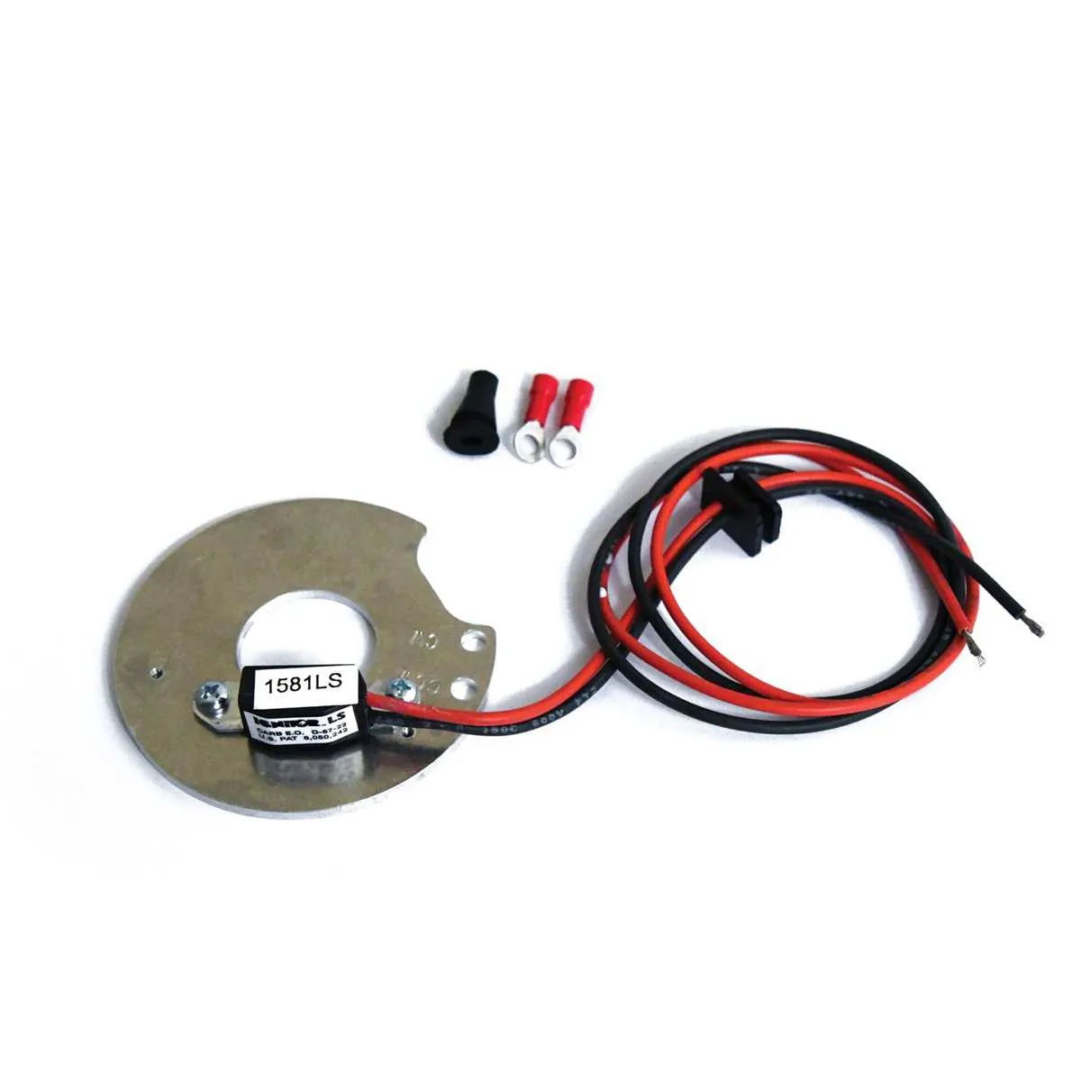
Make sure the trigger assembly is aligned correctly with the distributor’s shaft, as improper alignment can lead to misfires and poor timing. Secure the module to the mounting plate, ensuring it is positioned away from any interfering components. Once connected, proceed with testing the ignition system under idle conditions before full operation to confirm proper function.
Electronic Ignition Setup for Classic Engines
For a smooth conversion to electronic ignition, follow this step-by-step guide for proper connections. Ensure your components match the recommended specifications for maximum performance.
- Disconnect the battery before starting any work on the ignition system.
- Mount the electronic module on the distributor base, ensuring a secure fit.
- Connect the wire from the module to the coil’s positive terminal.
- Run the ground wire from the module to the distributor body or a nearby grounded part of the engine.
- Identify the power supply wire from the vehicle’s harness and connect it to the module’s power input terminal. Ensure this wire is protected with a fuse, if necessary.
- Connect the signal wire from the module to the coil’s negative terminal. This will carry the signal to trigger spark timing.
- Verify that all wires are correctly routed to avoid interference with moving parts or excessive heat.
Test the ignition system before reassembling any components. If the engine fails to start or misfires, check the wiring for loose connections, incorrect placements, or potential shorts.
For most applications, this setup provides reliable and consistent ignition timing with minimal maintenance. Regularly inspect for wear and ensure the module remains securely mounted to avoid any performance loss.
How to Identify Correct Wiring for Pertronix Ignitor Installation
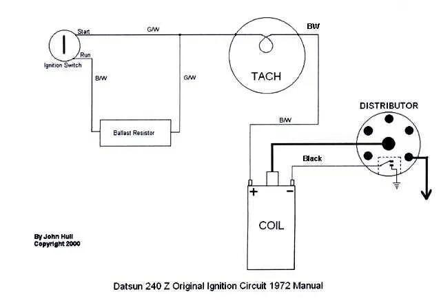
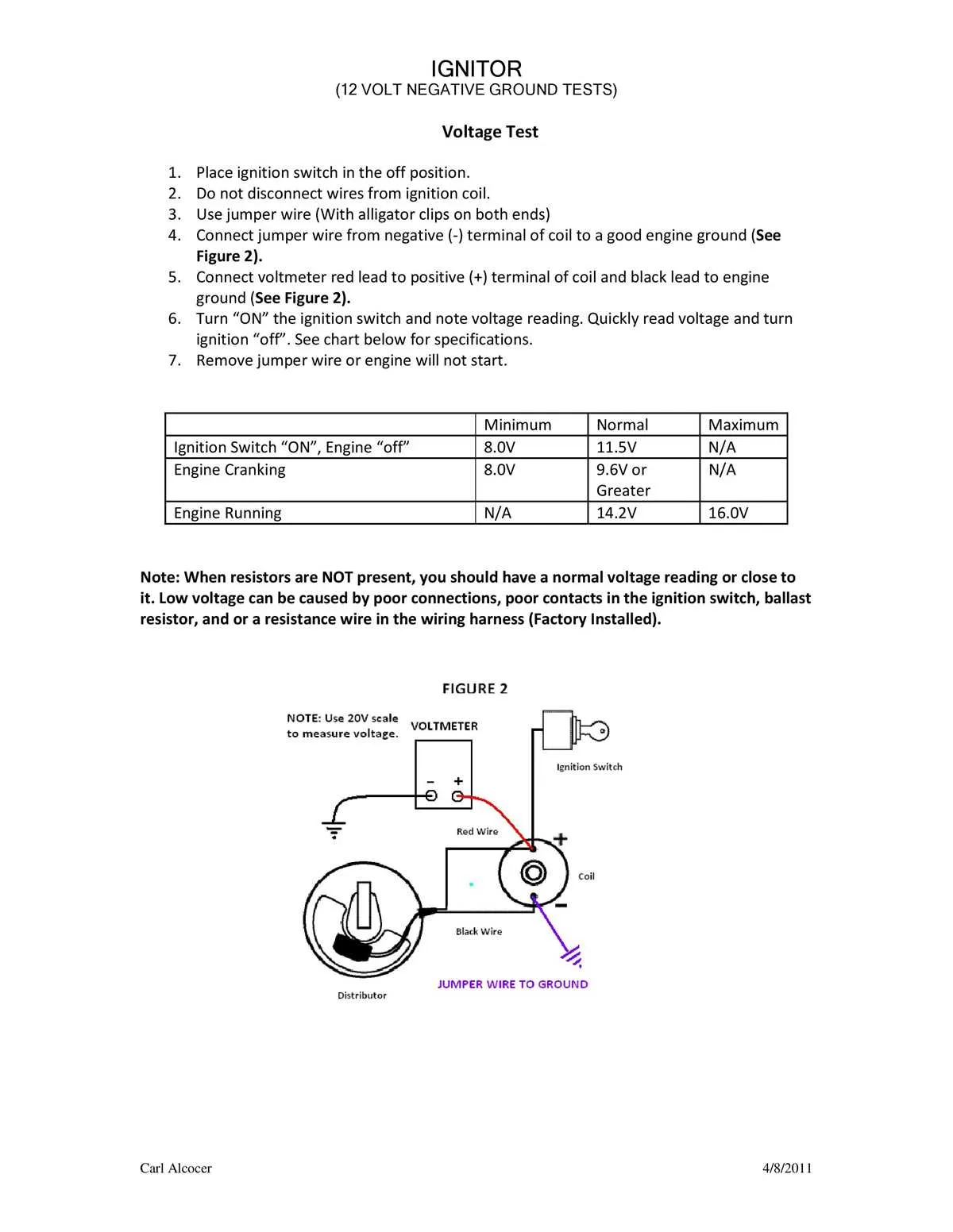
To ensure proper installation, start by confirming the power supply connections. The red wire should be connected to the ignition switch, and the black wire should link to the ground terminal. Always check for continuity and verify the polarity, as reversing wires may prevent the system from working properly.
Use a test light or voltmeter to check the voltage at the connection points. The red wire should receive 12V when the ignition is on. If it does not, check the ignition circuit for faults. Grounding issues are another common cause of malfunctions, so confirm the black wire is securely attached to a clean metal surface.
Next, identify the coil terminals. The positive terminal typically connects to the red lead, while the negative terminal connects to the black lead. Ensure these connections are solid, with no corrosion or wear on the terminals. Inspect the coil and ignition switch for any faults before proceeding with installation.
If your system includes a condenser or other components, ensure those are connected according to the instructions. Verify that any additional parts do not interfere with the main circuit and that they are wired in the correct sequence.
Finally, double-check all connections for tightness and cleanliness. Any loose or dirty connection can lead to weak or intermittent performance. Once the installation is complete, test the system by starting the engine to confirm proper operation.
Common Wiring Mistakes and How to Avoid Them

Ensure all connections are clean and tight. Loose terminals can cause erratic engine performance or failure to start. Always strip wires carefully to prevent damage to the insulation, and never over-tighten terminal screws, as this can lead to broken or damaged connectors.
Confirm the correct polarity when connecting the power source. Reversing connections can lead to overheating or malfunction. Double-check the voltage requirements of your system to avoid damaging components by supplying too much or too little current.
Avoid using the wrong gauge wire. If the wire is too thin, it can cause excessive heat buildup and possibly lead to a short circuit. Refer to manufacturer specifications for wire size based on current demands.
Double-check the grounding setup. An improper ground connection can lead to signal interference and irregular performance. Make sure the ground wire is securely fastened to a clean, rust-free metal surface.
Do not skip securing the wiring along the engine bay. Loose wires are prone to getting damaged by engine heat, movement, or contact with moving parts. Use wire looms and ties to keep the cables in place and away from hot surfaces.
Ensure the correct orientation of the components when installing them. Installing parts incorrectly can result in operational failure or potential damage to the system. Verify each piece against the installation manual before proceeding.
Step-by-Step Guide to Troubleshooting Pertronix Ignitor Wiring Issues

1. Check the Power Source: Verify that the electrical supply is stable. A weak or intermittent power source can lead to unreliable operation. Use a multimeter to confirm the voltage at the input terminal of the module. It should be consistent with the required voltage specified in the manual.
2. Inspect the Connections: Ensure all connections are secure. Loose or corroded contacts can cause inconsistent performance. Pay special attention to the terminals at both ends of the system. Clean or replace any damaged connectors.
3. Test the Coil: A malfunctioning coil can cause irregular firing. Measure the resistance between the positive and negative terminals of the coil. Cross-reference the resistance with the manufacturer’s specifications. If out of range, the coil needs to be replaced.
4. Verify the Signal Trigger: Check that the sensor and magnetic components are properly aligned. Misalignment can result in improper triggering of the spark, affecting engine performance. Ensure the air gap is within the recommended range.
5. Assess the Grounding: A poor ground connection can lead to electrical interference. Inspect the grounding points and ensure they are clean and free of rust or paint. A solid connection is critical for stable operation.
6. Check for Shorts or Open Circuits: Inspect the entire harness for any signs of short-circuiting or breaks. Use a continuity tester to ensure the wires are intact. Replace any faulty sections that could disrupt the current flow.
7. Test the Module: If all other components are functional, but the system still doesn’t operate as expected, the module itself may be faulty. A specialized testing tool can help determine if the module is working correctly. If in doubt, replacing the module may resolve the issue.
8. Confirm System Compatibility: Ensure the ignition system is compatible with the rest of your vehicle’s electrical setup. Mismatched components can lead to performance issues. Refer to the manufacturer’s guidelines to confirm correct system configuration.