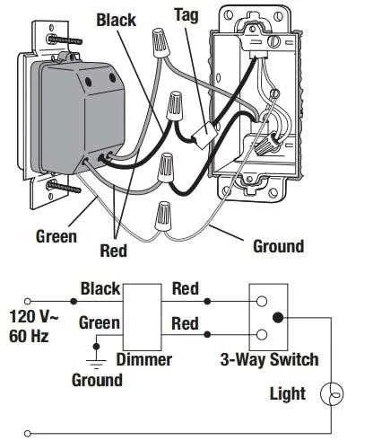
Begin by identifying the common terminal on both control units, typically marked or distinguished by color. Connect the incoming live conductor to this point to ensure proper power flow. Use traveler conductors–usually two wires of the same gauge but different colors–to link the corresponding terminals between the devices, allowing for synchronized operation from multiple spots.
For the adjustable lighting feature, locate the load terminal on the primary control device and run a conductor directly to the light fixture. Ensure that neutral wires remain continuous and uninterrupted throughout the circuit to maintain safe and stable function. Ground connections must be securely attached to the grounding terminals or wire nuts, complying with local electrical codes.
When installing, avoid mixing line and load conductors on the traveler terminals, as this can cause malfunction or damage. Use a voltage tester to verify all connections before final assembly, and consider consulting manufacturer-specific wiring schemes since terminal arrangements may vary slightly between brands and models.
Connecting a Dual-Location Light Controller
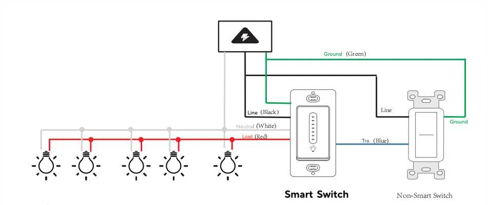
Begin by identifying the traveler cables running between the two control points. Attach these conductors to the designated traveler terminals on each device. The common terminal on the first unit must connect to the line (hot) wire supplying power, while the common on the second device links to the lighting fixture’s load wire.
Ensure the neutral conductors from the power source and fixture are joined together with a wire nut, as these do not connect to the controllers directly. Ground wires should be secured to the green grounding screws or grounding system within the electrical boxes.
Use wire nuts rated for the gauge of wires involved and double-check all connections for tightness to prevent arcing. Confirm that the devices are compatible with the type of bulbs used (LED, incandescent, CFL) to avoid malfunction.
After securing all terminals, carefully tuck wires into the boxes and mount the units. Restore power and test functionality, verifying that brightness adjusts smoothly from either control point.
How to Identify and Connect Traveler Wires Correctly
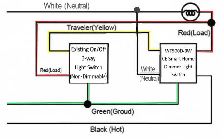
First, distinguish the traveler conductors by their insulation color–most commonly red or black–and confirm with a voltage tester that they are not energized before handling. Use a continuity meter to trace these leads between the two control points, ensuring they connect only to their respective terminals on each device.
Connect each traveler conductor to the corresponding traveler terminal on both controllers, avoiding cross connections. Secure terminals tightly to prevent loose contacts, which can cause flickering or malfunction.
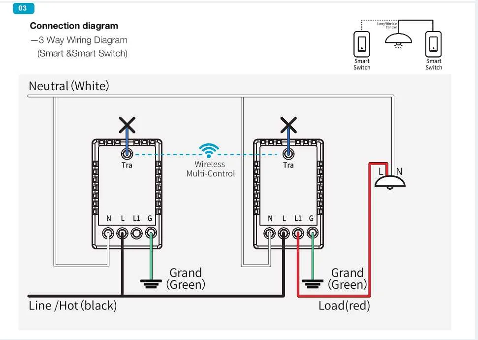
When labeling wires, mark each traveler with tape or tags to maintain clarity during installation and future maintenance. Avoid mixing traveler wires with the line or load conductors to prevent circuit errors.
Confirm proper function by testing both controllers after completing connections: toggling either should adjust the lighting without interruption or unintended operation. If issues occur, recheck traveler continuity and terminal placement.
Steps to Replace a Standard Triple-Position Control with a Light Level Adjuster
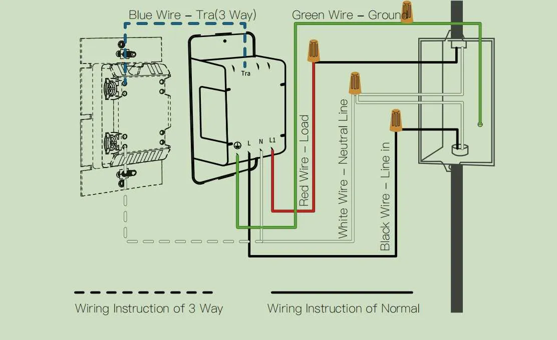
Begin by cutting power at the circuit breaker to avoid electrical hazards. Verify the absence of current with a voltage tester.
- Remove the existing triple-location toggle device by unscrewing the faceplate and mounting screws.
- Identify and label the traveler wires connecting the two controlling points; these usually have distinct colors, often red and black.
- Disconnect the common conductor, typically attached to a differently colored screw (often black or dark bronze).
- Detach the remaining traveler leads carefully, noting their positions for proper reconnection.
- Attach the common conductor to the designated terminal on the new light-level controller, usually marked as “common” or “COM.”
- Connect the traveler leads to the corresponding traveler terminals on the device, ensuring correct pairing based on prior labels.
- Secure the ground wire to the green grounding screw or grounding terminal to maintain safety compliance.
- Fasten the new device into the electrical box, reinstall the faceplate, and restore power at the breaker.
- Test functionality by adjusting illumination levels at both control points, confirming smooth operation and proper load response.
If any malfunction or flickering occurs, double-check connections and confirm compatibility with the lighting fixture’s load type.