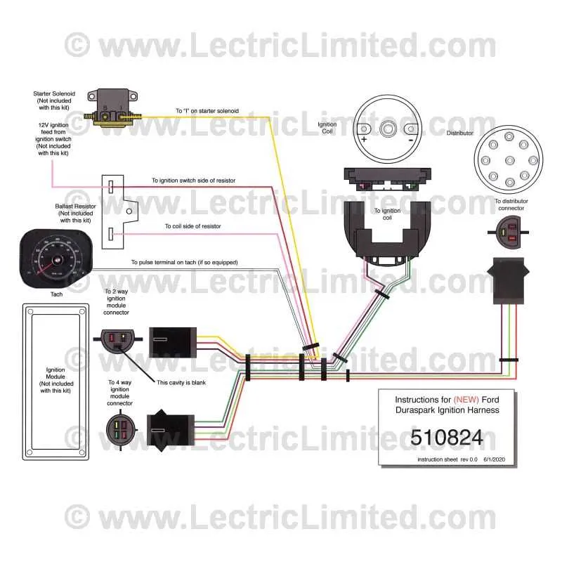
Begin by linking the ignition module’s green wire directly to the negative side of the coil. This connection is essential for proper timing control and spark discharge. Ensure the black wire from the module is grounded to a clean, paint-free surface on the engine block or chassis.
Connect the orange and purple leads from the control box to the magnetic pickup on the distributor. Polarity matters–reversing these will result in erratic timing. The orange wire should go to the stator’s positive output, and the purple to the negative.
Supply switched 12V power to the red input wire on the control module. This source should be active only during run and start positions of the ignition switch. Avoid using resistance wire in this circuit, as it can cause misfires or hard starts.
For consistent voltage under cranking, route a separate lead from the starter solenoid’s “I” terminal to the coil’s positive side. This bypasses any ballast resistance during engine start-up and ensures full spark energy when cold starting.
To test functionality, use a voltmeter to confirm 12V at the red input with the key in both RUN and START. Verify continuity between the coil negative terminal and the green wire at the module. A flashing test light on the coil negative when cranking indicates proper triggering.
Precise Connections for System II Ignition Setup

Begin by securing a reliable ground from the control module case to the chassis. A poor connection here will result in weak or no spark.
- Red wire: Connect to a 12V source that is hot in both start and run positions. This energizes the module and powers the internal circuitry.
- White wire: Route to the “S” terminal on the starter solenoid. This engages timing retard during cranking for easier starts.
- Orange and Purple leads: Connect these to the magnetic pickup in the distributor. Polarity matters – incorrect orientation can cause timing issues. If the engine kicks back or struggles to start, reverse them.
- Green wire: Leads to the negative side of the ignition coil. This line handles spark triggering, so ensure tight connections to avoid intermittent misfire.
- Black wire: Ground to the engine block. Clean contact point required – avoid painted or rusted surfaces.
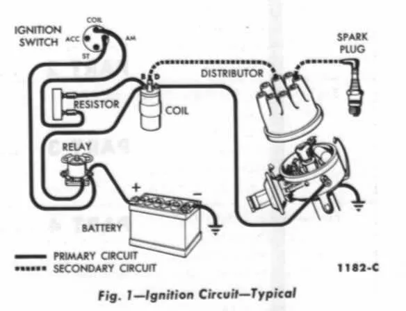
Bypass any ballast resistor if present, as this configuration demands full voltage to the coil during both start and run modes. Use a voltmeter to confirm at least 12V at the coil positive terminal under load. Failure to maintain voltage here can result in weak spark output and high-RPM failure.
How to Identify and Connect Duraspark 2 Module Wires by Color Code
Start by locating the following five primary conductors on the ignition control box:
Red wire: Connects to a switched 12V source; ensures the module receives power only when the ignition is on.
White wire: Routes to the starter solenoid’s “I” terminal; this delivers voltage during engine cranking for cold start enrichment.
Blue wire: Leads to the magnetic pickup inside the distributor; paired with the orange line, it carries signal pulses for spark timing.
Orange wire: Also connects to the distributor’s pickup; it must be installed with correct polarity relative to the blue one–reverse connection can cause timing errors.
Black wire: Grounds the control unit; secure this lead to clean chassis metal for stable operation.
Optional connectors: Some setups include a green line that links to the ignition coil negative post for tach feedback–verify if your configuration requires this before hooking it up.
Connecting the System to a Ford Ignition Coil and Distributor
Begin by linking the orange wire from the control module to the negative side of the ignition coil. The red wire must be tied to a switched 12V source that also powers the positive side of the coil. Avoid connecting the module directly to constant battery voltage – always use a source that is live only when the key is in the RUN or START position.
The purple and green leads from the module interface directly with the distributor pickup. The green wire connects to the pickup’s negative terminal, while the purple line links to the positive side. Reversing these leads will disrupt spark timing, so polarity must be verified.
Use a ballast resistor or resistance wire (typically around 1.3 ohms) in series with the coil’s positive terminal unless the coil is rated for full 12V operation. Bypassing this resistor during engine cranking is critical – use a dedicated start circuit to provide full voltage to the coil via the red/blue wire during start-up.
Ensure all ground connections are clean and tight. The module case must be securely grounded to the chassis to avoid misfires. Do not rely on paint-coated surfaces; use a dedicated ground strap if needed.
Troubleshooting Common Duraspark 2 Wiring Mistakes and Ignition Failures
Start by verifying that the ignition module is securely grounded to a clean, unpainted metal surface. A missing or corroded ground connection often leads to intermittent spark or complete no-start conditions.
Check the resistance of the magnetic pickup coil inside the distributor using a multimeter. The correct range is typically between 400 and 800 ohms. Readings outside this range indicate a failed pickup, which can disrupt timing signals to the control unit.
Ensure the red power feed wire receives a full 12V in both run and start positions. Using a ballast resistor or sourcing voltage from a reduced-voltage feed will result in weak or no spark under load.
Inspect the connections at the module plug for bent pins or pushed-back terminals. Poor contact at this junction often causes misfires under acceleration or sudden stalling.
Confirm the coil’s primary and secondary resistance. The primary side should measure between 0.6 to 1.6 ohms, while the secondary should fall between 6,000 and 10,000 ohms. Deviations suggest coil breakdown, especially under heat.
Route all control wires away from high-voltage components like the ignition coil or spark plug leads. Inductive interference can confuse signal timing and trigger false module shutdowns.