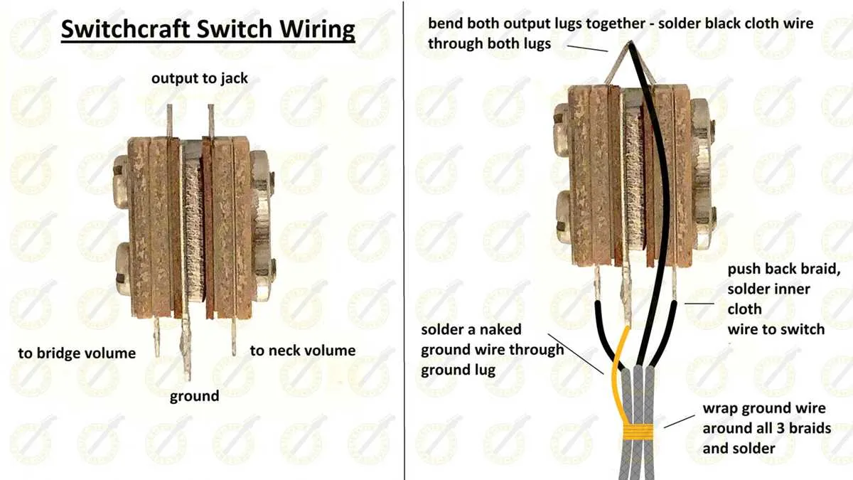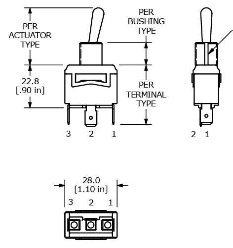
Begin by identifying the two main terminals on your selector device: the input power line and the output load connection. Ensure the power source is disconnected before making any attachments to prevent hazards. Use a multimeter to verify continuity and voltage levels on each terminal prior to installation.
For a single-pole application, connect the live wire directly to the input terminal and route the output lead to the device you intend to control. Ground connections should be secured to the chassis or designated earth point for safety compliance. Avoid mixing neutral and hot lines within the controller to prevent malfunction.
When implementing a double-throw configuration, connect the common terminal to the power source and run two separate leads to the intended circuits. This setup allows selection between two outputs, enabling alternate control paths without rewiring.
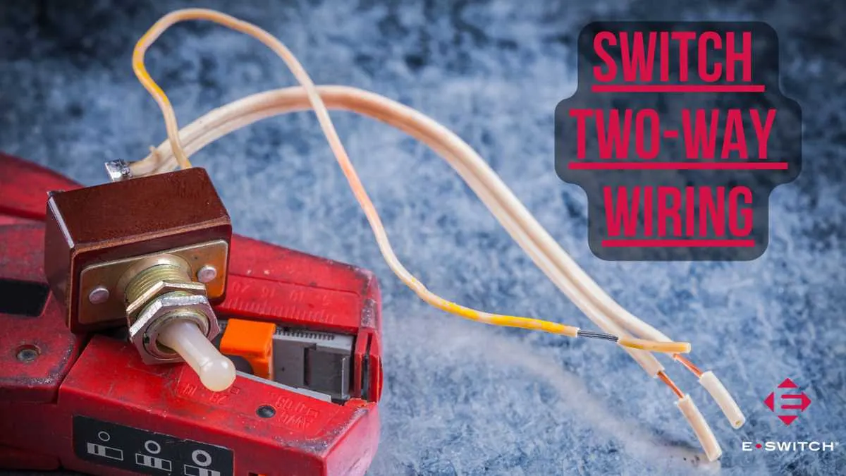
Connecting a Toggle Mechanism: Essential Instructions

Begin by identifying the two main terminals: the power input and the output line. Connect the live wire from the power source directly to the input terminal of the control device. The output terminal must then be linked to the load’s positive side.
Grounding is crucial–attach the ground wire to the dedicated terminal or chassis to ensure safety and prevent electrical faults.
Use insulated, appropriately rated cables (minimum 16 AWG for standard 12V circuits) to prevent overheating and signal loss. Secure all connections with crimp terminals or solder joints to maintain stability under vibration or movement.
When dealing with a double-pole control element, repeat the process for the secondary circuit, ensuring each pole handles its designated line without crossover.
Test the continuity using a multimeter before final assembly. Confirm that toggling the actuator completes and breaks the circuit cleanly, avoiding shorts or incomplete contacts.
Identifying and Preparing Wires for Installation
Always begin by locating the power source cable and confirming its voltage with a multimeter before proceeding.
- Determine Wire Types:
- Hot conductor: Typically black or red insulation, carries current to the device.
- Neutral conductor: Usually white or gray, completes the circuit.
- Ground wire: Bare copper or green insulation, ensures safety by grounding.
- Inspect Wire Condition:
- Check for insulation damage, cracks, or corrosion.
- Replace any wires with compromised integrity.
- Prepare Cable Ends:
- Strip insulation to expose ¾ inch (about 19 mm) of bare conductor.
- Use wire strippers matching the conductor gauge to avoid nicking.
- Label Conductors:
- Mark each wire with colored tape or tags corresponding to its function.
- Document the configuration for future reference and troubleshooting.
Properly preparing and identifying each conductor ensures a safe and efficient installation process.
Connecting Power, Load, and Ground Wires Correctly

Attach the power conductor directly to the input terminal of the control device, ensuring a secure and clean connection to avoid voltage drops. Use a conductor rated for the circuit’s amperage–typically 14 AWG for up to 15 amps, 12 AWG for 20 amps, and thicker for higher loads.
Connect the load wire to the output terminal that leads to the device being controlled. Confirm that the load conductor matches the device specifications and is insulated properly to prevent shorts or interference. Avoid looping the load wire back to the power source.
Ground the assembly by fastening the ground conductor to the grounding terminal or screw, usually marked in green or bare copper. This ensures safety by diverting fault current. Use a dedicated grounding path connected to the main grounding system of the installation.
Verify all terminals are tightened to manufacturer torque values–usually around 12 to 15 inch-pounds–to maintain mechanical stability and consistent electrical contact. Double-check that no insulation is stripped beyond the terminal area to prevent exposure of bare wire outside the connector.
Testing the Toggle Switch Wiring for Proper Functionality
Use a multimeter set to continuity mode to verify the connections. Place the probes on the input and output terminals of the control device. When flipped to the ON position, the meter should beep or show near-zero resistance, confirming a closed circuit. In the OFF position, the reading must indicate no continuity.
Check for secure terminal connections by gently tugging the wires to ensure no looseness. Inspect solder joints or connector crimps for cold joints or corrosion, which can cause intermittent faults.
Power the circuit with the specified voltage and observe the controlled device’s behavior. Confirm that activation occurs only when the actuator is engaged, and deactivation happens immediately when released. Any delay or erratic function signals a wiring error or faulty component.
For three-way or multi-pole variants, test each position individually using the continuity tester. Validate that each terminal correctly opens or closes the circuit according to the intended operational mode.
Document all test results and mark any deviations for troubleshooting. Repeat tests after adjustments to guarantee consistent performance before final installation.