devices and Directive /95/EC Annex III on the use of electrical equipment within certain voltage limits. The manufacturer ..
against unauthorized activation . ..
System diagrams of single-line centralized lubrication systems, Fig. 3.

M. T.
P . Dual Line system. Document No.
EN. M. Software manual for.
LMC PC Software. Single Line lubrication system. Document No.

A. Light Stays On.
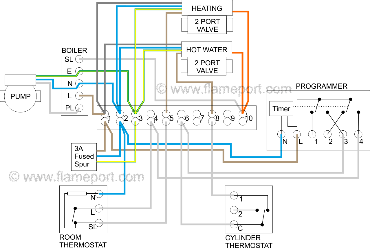
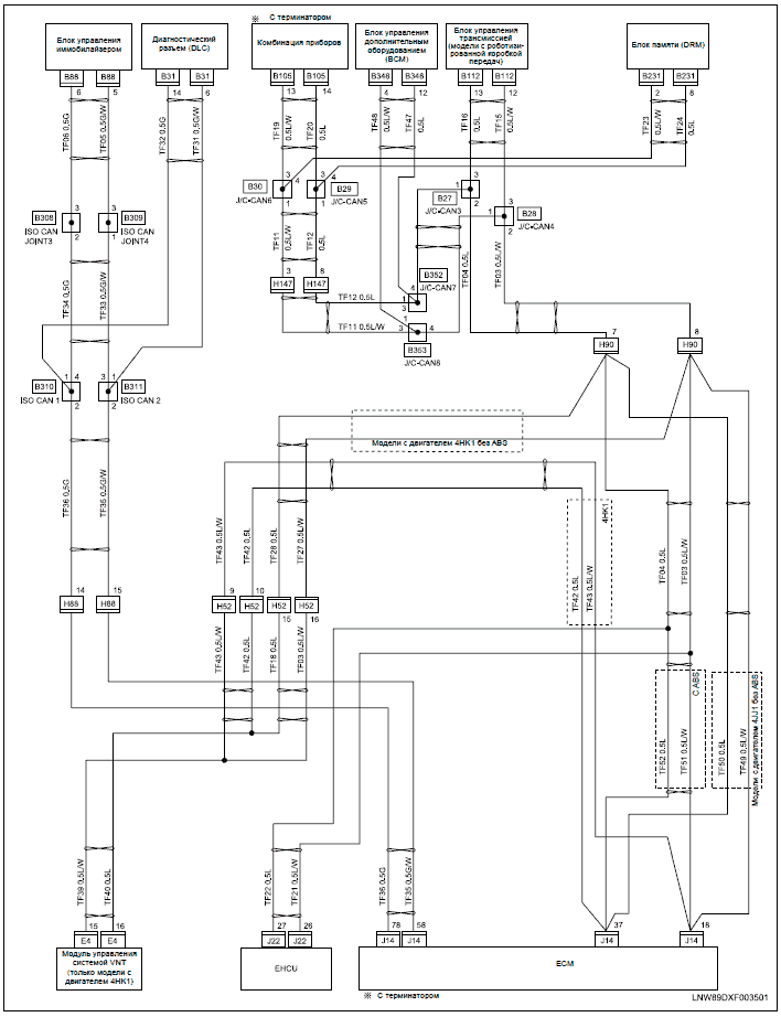
Wiring Diagram. Common SKF Monoflex system parts.
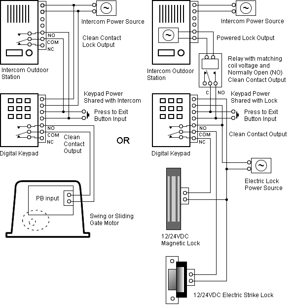
N. SKF The KFU pump is activated by the IGE control unit. The.
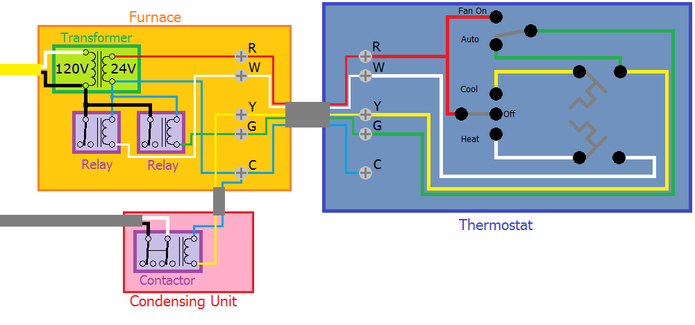
Pneumatic central lubrication system pump. EN Pneumatic lubrication pump for vehicle lubrication systems turning the valve’s manual activation screw.
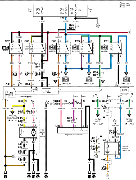
For use in centralized lubrication systems Read this owner’s manual before installing, operating or .. Activate intermediate lubrication.Chain lubrication, accessories Nozzles, oiling brushes, reservoirs and other accessories for chain lubrication Open the catalogue to page 1 Chain lubrication systems, accessories Oil projection nozzle AC-A Compact design, pinpoint accuracy, and high temperature resistant, the projection nozzles AC-A are perfectly suited to aggressive surroundings.
the Acessories only with SKF actuators and SKF control units!
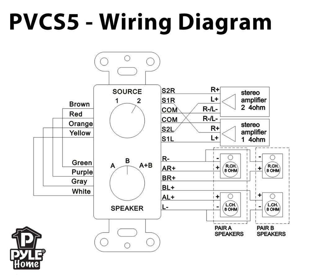
Electrical operating elements (foot switch, hand switch and desk switch): EHA1, STF, STA: The de vices are intended to operate 1 to 5 actuation SKF drives with the control units KOM1, KOM3, KOM3T, MCU or to operate MAX6 linear actuator with integrated con – trol unit. About SKF USA Inc., Actuation Systems Company Description by ThomasNet Manufacturer of a complete range of actuator products (linear actuators, telescopic pillars, electromechanical actuators, ball screw actuator, linear actuator motor) designed for the most demanding requirements.
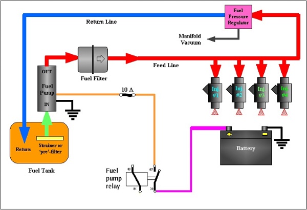
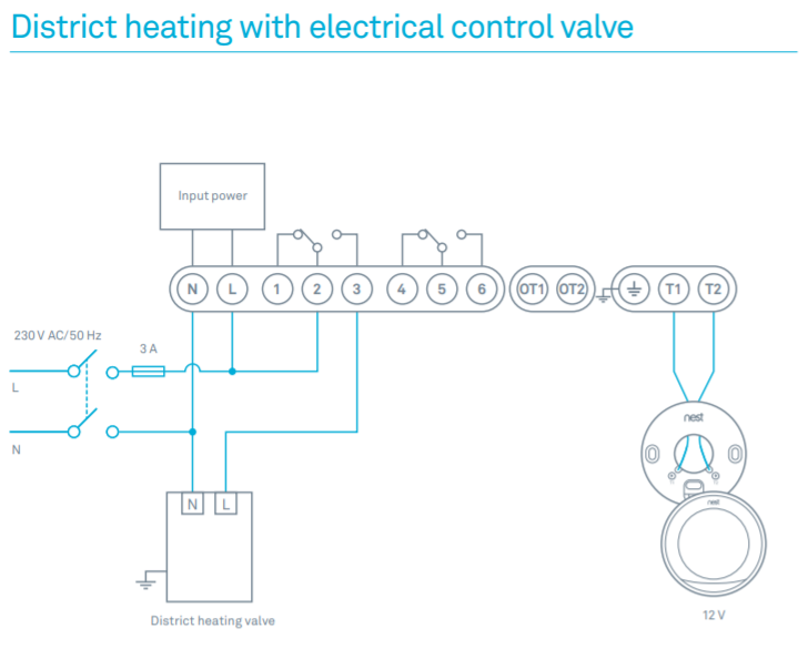
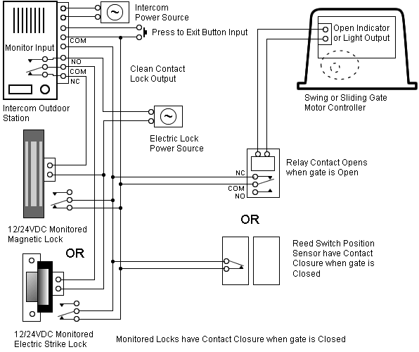
Skf Wiring Diagram. welcome to my blog here I will show you a little more what you are looking for Skf Wiring Diagram below there are some photos and a little about Skf Wiring Diagram that you can see and read, hopefully in accordance with what you are looking for.
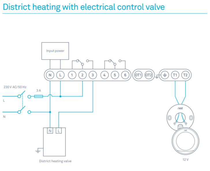
ACTUATOR WIRING DIAGRAMS. schematron.org 1 WIRING DIAGRAM DIRECTORY. On/Off, Regulating, 12VDC, 2.
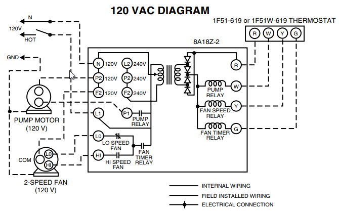
Diagram. Diagram EH3 Description P/N Examples Wire Code Page Install actuator after ignition switch, or master power switch.Up in the air or deep in the sea, lubrication is key | Evolution OnlineGrease life in lubricated-for-life deep groove ball bearings | Evolution Online
