Connect the power supply directly to the control box terminals using heavy-gauge cables rated for at least 30 amps to ensure optimal current flow without voltage drop. Always integrate a properly rated inline fuse or circuit breaker within 12 inches of the battery connection to protect the system from short circuits and overloads.
Use color-coded leads: red for positive and black for negative terminals, maintaining consistent polarity throughout the installation. Secure all ground connections to a clean, unpainted metal surface on the vehicle chassis to prevent electrical resistance and signal interference.
Verify the relay control wiring by testing continuity before finalizing connections. Employ weatherproof connectors and seal all junction points with dielectric grease to minimize corrosion risks in off-road conditions. Adhering to these specifications maximizes performance reliability and safeguards both the vehicle’s electrical system and the hoisting equipment’s electronics.
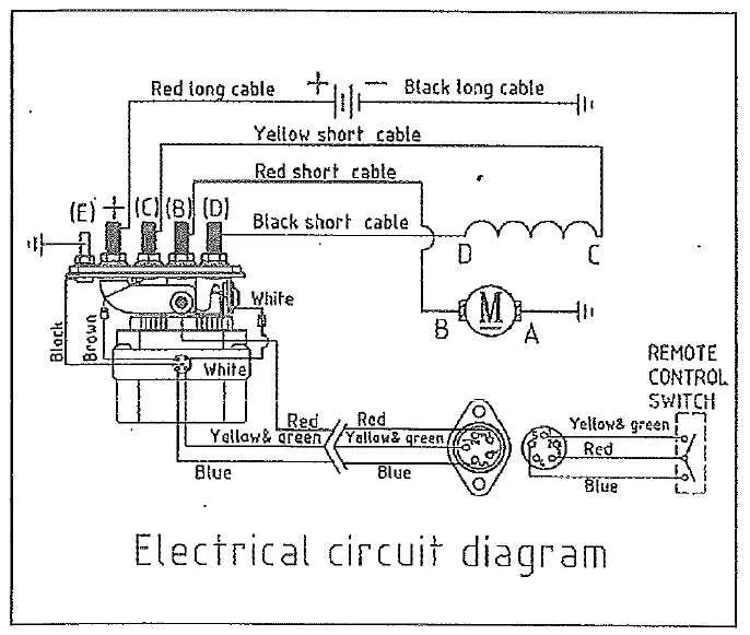
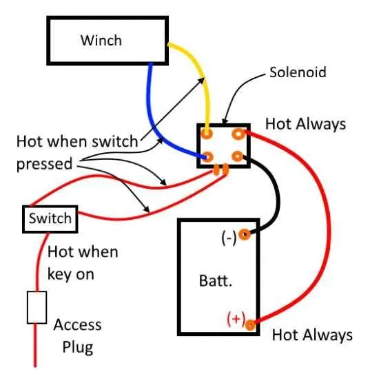
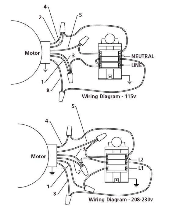
Electrical Schematic for Warn Winch Installation

Connect the positive battery terminal to the heavy-duty relay’s input using a minimum 8-gauge cable to ensure sufficient current flow. Ground the relay securely to the vehicle chassis with a clean, bare metal surface to prevent voltage drops.
Run a fuse rated at 30 amps inline near the battery connection to protect the circuit from overloads. Use color-coded wires: red for power feed, black for grounding, and blue for the remote control switch line for clarity during troubleshooting.
Attach the solenoid terminals to the motor leads precisely as specified in the manufacturer’s specifications, ensuring firm and corrosion-free connections. Employ waterproof connectors or heat-shrink tubing to prevent moisture ingress, which could cause electrical failure.
Incorporate a switch control box inside the vehicle cabin, wiring it through a dedicated relay trigger to minimize voltage drop over long distances. Confirm polarity carefully before finalizing connections to avoid damage to the motor or control module.
Test the entire circuit by operating the pulling mechanism with no load first. Verify that the relay clicks smoothly and the motor runs in both directions with immediate response to switch toggling. Address any sparking or heat buildup immediately by checking all contact points and wire gauge adequacy.
Choosing Correct Gauge Wire for Warn Winch Installation
Use a minimum of 4 AWG cable for most electric pulling device setups rated up to 8,000 lbs. For models with higher amperage demands or longer cable runs exceeding 10 feet, upgrade to 2 AWG to prevent voltage drop and overheating.
Battery-to-motor conductors must be as short as possible and sized to handle peak current, often exceeding 300 amps during startup. Undersized cables cause power loss and risk insulation damage.
For runs under 6 feet, 4 AWG is sufficient for loads up to 12,000 lbs. Between 6 and 15 feet, step up to 2 AWG. Beyond 15 feet, consider 1/0 AWG to maintain efficiency and safety margins.
Use copper-stranded wire with high strand count for flexibility and durability under vibration and movement conditions. Ensure all terminals are tightly crimped and corrosion-protected.
Step-by-Step Connection of Warn Winch to Vehicle Battery
Directly connect the power cable from the motor controller to the positive terminal of the vehicle’s battery, ensuring the cable gauge matches the specified amperage requirements, typically 4 AWG or thicker for optimal current flow.
Attach the ground cable from the controller’s negative terminal securely to the battery’s negative post or a solid chassis ground point free of rust and paint for reliable conductivity.
Install an inline fuse or circuit breaker rated for the maximum current draw, usually between 150 to 200 amps, on the positive lead within 18 inches of the battery terminal to protect the electrical system from overload.
Route the cables carefully to avoid sharp edges, moving parts, and excessive heat sources; use cable ties and protective sleeves to prevent abrasion and maintain neatness.
Confirm all connections are tight and corrosion-free; use dielectric grease on terminals to enhance durability and prevent oxidation over time.
Test the system by activating the control switch while monitoring voltage drops; a healthy connection should maintain above 12 volts under load without significant fluctuations.
Troubleshooting Common Electrical Issues in Warn Winch Systems

Start by verifying all connectors for corrosion or loose contacts, as poor conductivity is the leading cause of malfunction.
- Check Battery Voltage: Ensure the power source maintains at least 12.5 volts under load; lower readings indicate charging or cable issues.
- Inspect Ground Connections: Confirm that the negative terminal and chassis ground points are clean, tight, and free of paint or rust, preventing voltage drop.
- Assess Control Switch Functionality: Use a multimeter to test for continuity and proper signal flow through the remote or handle switch.
- Examine Solenoid Operation: Listen for a click when activating the control. Absence of sound suggests coil failure or insufficient input voltage.
- Trace Power Cables: Look for frayed insulation, pinched wires, or heat damage especially near mounting points or moving parts.
To isolate faults efficiently, perform voltage drop tests across key segments under operational load. Values exceeding 0.5 volts indicate resistance needing correction.
- Use dielectric grease on terminals to prevent oxidation.
- Replace any wiring showing discoloration or brittleness.
- Secure all cables away from sharp edges or pinch points.
Routine maintenance of electrical contacts and fasteners dramatically improves system reliability and reduces downtime caused by power delivery failures.