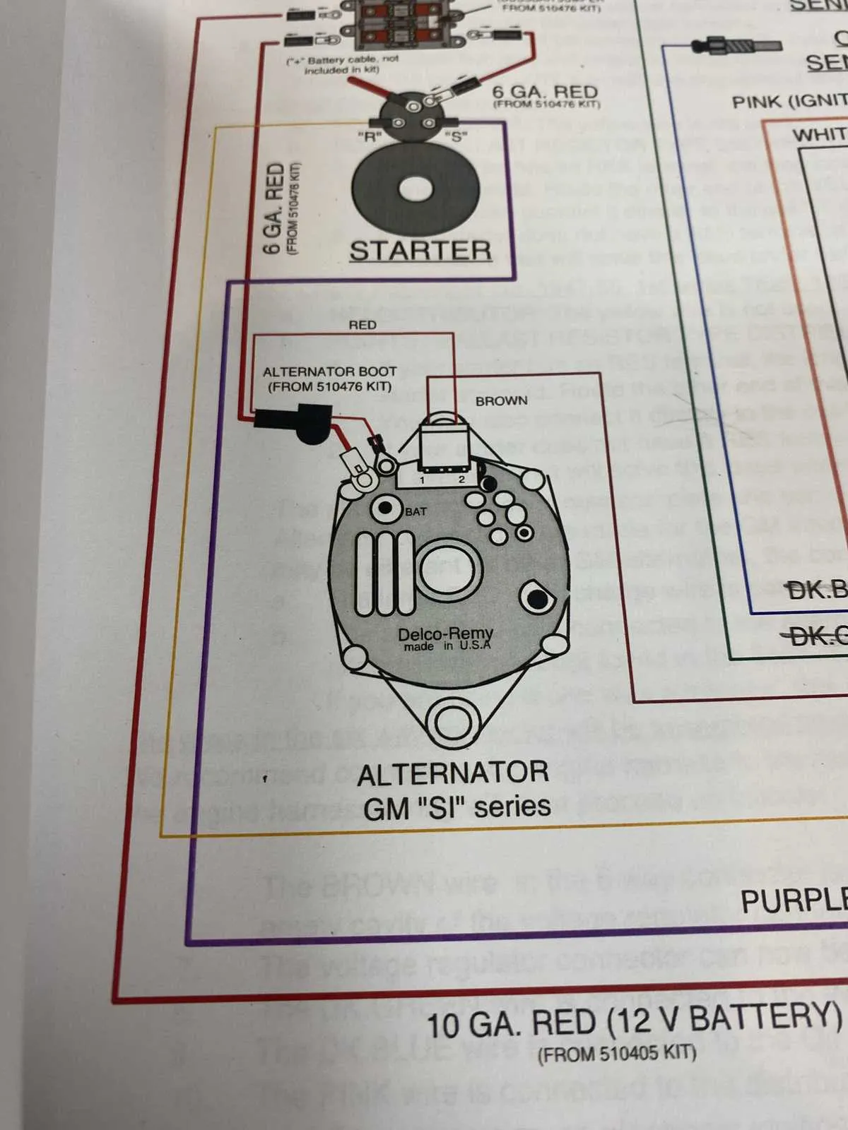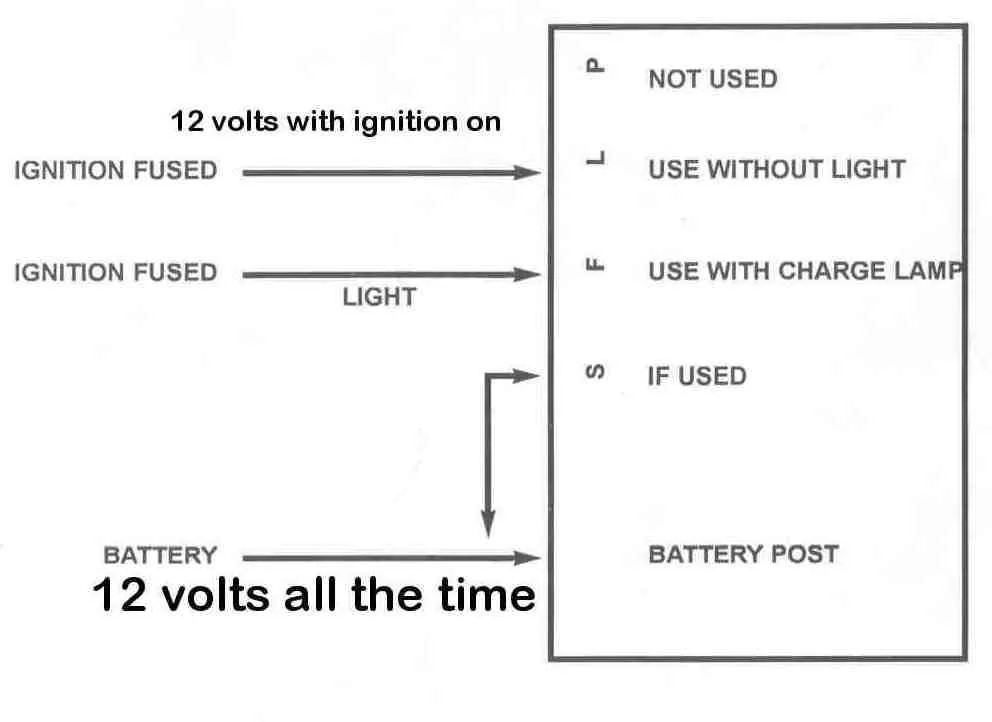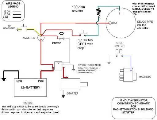
Ensure proper installation of your GM generator system by following the recommended connection guidelines. Start by identifying the key terminals on the unit: the battery terminal, ground, and the ignition switch input. It’s essential to connect the battery terminal directly to the positive lead from the vehicle’s power source to guarantee a stable voltage supply.
Next, connect the ground terminal securely to a clean, unpainted metal surface on the vehicle frame to ensure proper grounding. A poor ground connection can lead to intermittent power delivery, reducing the efficiency of your generator and causing electrical issues. Make sure all connections are tight and free from corrosion to prevent power loss.
For the input from the ignition system, wire the unit to the appropriate signal from the ignition switch to enable the charging process when the engine starts running. This connection activates the power generation process, which is crucial for maintaining a steady voltage supply to the vehicle’s battery. Use high-quality, insulated wiring to prevent shorts or electrical damage.
Remember, always verify the voltage output after installation using a multimeter. The typical voltage should be between 13.8V and 14.4V when the engine is running. If the reading deviates significantly from this range, check your connections and component health. With these steps, you can be confident that your GM power unit will operate effectively and reliably. Never bypass safety protocols when handling electrical components to avoid damaging sensitive equipment or risking personal safety.
GM Generator Electrical Connections

For proper connection of the GM charging system, ensure the following components are correctly linked. The key terminals are the “BAT” terminal, the “L” (Light) terminal, and the “F” (Field) terminal. The “BAT” terminal is used to connect the charging unit to the vehicle’s battery, while the “L” terminal triggers the warning light in the dashboard. The “F” terminal controls the voltage regulator and should be connected to the appropriate voltage regulator terminal.
The “BAT” terminal should be linked to the positive terminal of the battery using a thick gauge wire, capable of handling the system’s current demands. Ensure that the wire is tightly secured to avoid any loose connections that could lead to performance issues. The “L” terminal, often marked as “L” on most units, should be connected to the dashboard warning light, indicating whether the system is charging properly.
For the “F” terminal, verify the voltage regulator’s connections. This terminal controls the output voltage of the generator and needs to be wired to the regulator’s field terminal. A faulty connection here can lead to overcharging or undercharging, damaging electrical components in the vehicle.
Additionally, check the grounding of the charging unit. It is crucial to ensure that the body of the generator is properly grounded to avoid erratic behavior or failure in electrical systems. A dedicated ground wire from the generator casing to the vehicle frame is recommended to ensure a stable connection.
Finally, make sure the belt tension on the generator is correct. If the belt is too loose, it can slip and cause poor electrical output. If it’s too tight, it may cause excessive wear on the bearings, reducing the generator’s lifespan.
How to Identify Key Wires in a GM Alternator Setup

Start by locating the field terminal, typically labeled “F” or “L”. This wire is responsible for controlling the charging voltage and is critical for the proper operation of the system. It’s usually a small gauge wire that connects to the regulator or control module.
Next, identify the battery terminal, marked as “B+”. This larger wire connects directly to the positive battery terminal, delivering charging current from the unit. It is often thick and insulated for high current transmission.
The ground wire, often denoted as “GND” or simply connected to the frame of the vehicle, ensures the proper grounding of the unit. This is essential for safety and the correct functioning of the system. It may be connected to the alternator housing or chassis.
Look for the sense wire, frequently found on newer models. It monitors the battery voltage and adjusts the output voltage accordingly. This wire typically connects to the battery side of the vehicle’s electrical system.
Check the indicator light wire, which is often linked to the dash light. This wire communicates if the system is charging correctly. If this light remains on, it may signal a malfunction in the voltage regulation.
Ensure all connections are properly secured and check for signs of wear or corrosion. Each wire must be correctly routed to ensure accurate power delivery and system performance.
Step-by-Step Guide to Properly Connect the GM Alternator Wires
Start by ensuring the vehicle’s ignition is turned off and the battery is disconnected before proceeding with any connections. This will prevent accidental electrical shorts and damage to components.
First, identify the main output terminal, typically marked as B+ or a similar label. This terminal is where the large gauge wire from the battery’s positive terminal connects. Use a sturdy, corrosion-resistant connector to ensure a secure and reliable connection. Tighten the bolt firmly but avoid over-tightening to prevent damaging the terminal.
Next, connect the smaller wire that controls the field current to the designated terminal. This wire regulates the charging process and is often color-coded (usually green or purple). Use a spade terminal and make sure it’s securely attached, as a loose connection can cause inconsistent charging performance.
Locate the sense wire terminal (often labeled S or F). This wire helps the system monitor voltage levels, ensuring the generator charges the battery correctly. Attach it to the appropriate pin and ensure the connection is clean and free of corrosion. If necessary, use a dielectric grease to prevent moisture buildup and electrical resistance.
For the ground connection, ensure that the ground strap is firmly attached to the frame or engine block. A poor ground can lead to erratic performance and may even prevent the unit from charging properly.
Finally, double-check all connections before reconnecting the battery and testing the system. Look for any signs of wear, loose fittings, or exposed wires that could cause short circuits. Once everything is secure, reconnect the battery and start the engine to confirm that the charging system is working as expected.
Common Electrical Issues in GM Charging Systems and How to Fix Them
Start by checking for damaged or frayed wires, especially near the connectors. These are often the cause of inconsistent charging behavior. If you notice any visible damage, replace the wire or connector immediately to ensure a stable connection.
If the system is not producing enough power, the voltage regulator might be faulty. Test it by measuring the output voltage at the charging point. A properly functioning system should provide between 13.8V and 14.4V. If the voltage is below this range, replace the regulator.
- Corroded Terminals: Corrosion on the terminals can lead to poor electrical contact. Clean the terminals thoroughly with a wire brush and apply a protective coating to prevent future corrosion.
- Poor Ground Connection: A weak or loose ground connection can cause unreliable power delivery. Inspect the ground wire for tightness and clean the contact points. Ensure it’s properly grounded to the vehicle’s frame.
- Loose or Faulty Belt: The belt driving the generator may wear out or loosen over time. Check for proper tension and signs of wear. A loose belt can lead to undercharging.
If you experience intermittent charging issues, verify the connection at the junction box or fuse box. Loose fuses or improper connections here can cut off power intermittently.
- Ensure the fuse is intact and properly seated.
- Inspect for any rust or dirt accumulation inside the fuse box and clean it carefully.
Lastly, check the condition of the diode bridge, which converts AC to DC. A faulty diode can cause erratic charging behavior. Test each diode using a multimeter and replace any that fail the test.