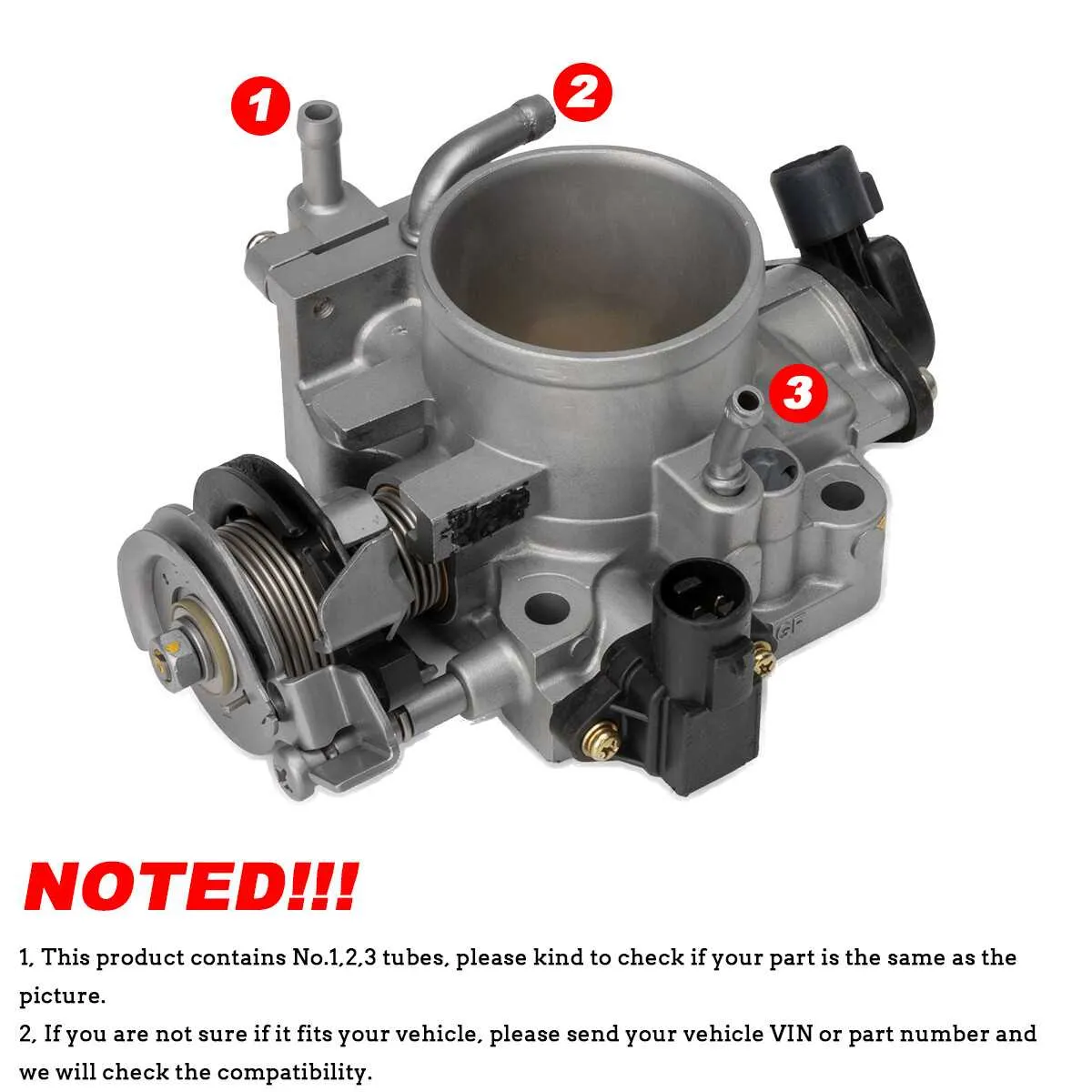
Ensure correct routing of all vacuum lines in the intake manifold system to prevent any performance issues in the air control system. A precise connection between components like the air intake, valve assemblies, and sensors is critical to maintain engine efficiency. Follow the outlined steps to confirm that the vacuum connections are intact and secure.
Start by checking the connection points on the intake manifold. The vacuum hoses should align with the designated ports on the intake manifold and throttle control unit. Use durable hose clamps to secure each connection to avoid any air leaks.
Next, inspect all components for signs of wear, such as cracks or holes in the vacuum lines. Replace any compromised lines immediately. Use replacement hoses that match the original specifications to avoid issues with air flow. Also, check the connectors and seals, as improper sealing can lead to inefficiencies in the air intake process.
Ensure that each sensor–such as the mass air flow sensor and idle air control valve–has a secure connection to the corresponding ports on the intake manifold. If any sensor shows signs of malfunction or disconnection, it’s important to address it promptly, as these components play a significant role in maintaining optimal engine performance.
By regularly checking and maintaining these connections, you can ensure smooth engine operation and prevent long-term damage to critical air intake systems.
Proper Routing of Vacuum Lines in Engine Components
Ensure correct connection of the vacuum tubes to the intake manifold area to prevent air flow issues. Follow these steps:
- Connect the main intake tube to the air intake sensor port.
- The idle air control valve (IACV) should be linked to the manifold via a dedicated line.
- Verify the EGR valve is connected properly to avoid exhaust gases entering the intake.
- Ensure the secondary vacuum line routes from the manifold to the cruise control system.
- The MAP sensor should have a direct vacuum feed to avoid fluctuation in sensor readings.
- Check that the line for the purge valve is free of leaks to prevent improper fuel vapor handling.
Failure to follow these routes may result in poor engine performance and increased emissions. Always double-check the connections before starting the engine.
Identifying the Correct Routing for Engine Intake Connections

Start by ensuring that the vacuum and air intake connections are properly routed to avoid engine performance issues. Confirm that the vacuum line from the intake manifold is securely connected to the intake valve control unit, ensuring there are no leaks. This connection should follow the path indicated in the vehicle’s service manual, which provides specific routing instructions for each component.
The next step is to inspect the air control tubes. Ensure that the connection from the air filter housing is tightly fastened to the intake system. This part should be free from cracks, and the clamps should be securely tightened to prevent air leaks. Pay attention to the routing of the intake duct, as any deviation can lead to improper airflow and diminished engine response.
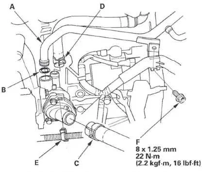
Check the cooling system’s routing by verifying the correct placement of the coolant hoses. These should be connected to the designated ports without obstruction. It’s important to avoid kinks in the lines, which can restrict fluid flow and cause overheating issues.
Finally, double-check the positioning of all electrical connectors near the intake manifold. These should be correctly aligned to prevent any interference with the air and fuel systems. Proper alignment ensures efficient engine operation and prevents malfunctioning sensors from affecting vehicle performance.
Common Issues with Connection Problems and Fixes
Check for cracks in rubber components that may lead to air leaks, affecting engine performance. Inspect all parts carefully, especially around areas exposed to heat. Replace any cracked or brittle rubber with high-quality replacements to prevent further damage.
Ensure tight fittings at each junction. Loose clamps or worn-out connectors can cause a loss of vacuum pressure, leading to poor engine response. Tighten connections securely and replace damaged clamps to restore proper airflow.
Inspect for wear on flexible tubes. Over time, constant movement can cause these components to degrade. Examine the flexible sections for signs of wear and replace them immediately to avoid leaks that disrupt the engine’s air intake system.
Clean connectors regularly to remove dirt and debris that may cause a poor seal. Dirt can accumulate around junctions, preventing a proper connection and compromising the engine’s performance. Use a clean, dry cloth to wipe down all connectors before reassembling.
Verify alignment during reassembly. Misaligned components can create gaps and cause improper sealing. Check that all parts are properly aligned before tightening any clamps or fasteners. This ensures a tight, efficient seal throughout the system.
Replace damaged fasteners if necessary. Rust or corrosion on metal fasteners can interfere with proper connection. Ensure that all fasteners are in good condition, replacing any corroded ones to avoid system failure.
Test after repairs by monitoring engine idle speed and performance. After replacing or fixing any components, start the engine and observe for any unusual sounds, such as sputtering or rough idling. This can indicate that air is still leaking, requiring further adjustments.
Step-by-Step Guide to Replacing Air Intake Connectors
1. Disconnect the battery to prevent any electrical issues while working. This step is critical before starting any repair involving engine components.
2. Remove the engine cover if necessary. Some models require this to gain access to the intake system. Use a screwdriver or socket wrench to remove the fasteners.
3. Locate the intake system’s rubber connectors and inspect them. Identify any cracks, wear, or tears that might affect performance. A damaged connector can lead to poor engine response or air intake issues.
4. Loosen the clamps securing the damaged parts. Use a flathead screwdriver or a clamp tool to loosen and remove the clamps that hold the parts in place. Be careful not to damage any surrounding components while doing so.
5. Remove the faulty part from the intake system. Once the clamps are loose, pull the damaged section off gently. If it’s stuck, lightly twist to break any seal without using excessive force.
6. Install the new component in the reverse order. Slide the new connector into place, ensuring it fits snugly against the intake manifold and throttle assembly.
7. Secure the component with the clamps you removed earlier. Tighten them securely but not too much, as over-tightening can damage the rubber seals.
8. Test the system before reassembling the engine cover. Start the engine and listen for any air leaks. If the engine runs smoothly without unusual noises or a check engine light, the replacement was successful.
9. Reattach the engine cover if applicable, and reconnect the battery. Ensure all connections are tight before finishing the procedure.