To ensure optimal functionality of your towing setup, it’s crucial to correctly configure the system that links your vehicle to the trailer. A proper installation of the electrical connections allows for smooth operation of signals, lights, and essential braking features on the trailer. The key to this lies in understanding how to wire the system in a way that guarantees safety and performance.
Start with proper grounding. Grounding is one of the most important elements to prevent electrical issues and interference. A reliable ground connection reduces the risk of faulty connections, ensuring all components function as intended.
Use a dedicated circuit for each function. For example, separating the brake controller’s power source from the running lights will prevent overloading and ensure each system operates independently. This approach minimizes the risk of malfunction due to power fluctuations.
Finally, ensure that all connections are secure and insulated to prevent corrosion. This is particularly important when dealing with environments that expose your vehicle to moisture or extreme temperatures. Regular maintenance and inspection of the connectors can extend the lifespan of the system and improve its efficiency.
Essential Guide to Electric Connection Setup for Towed Vehicle Systems

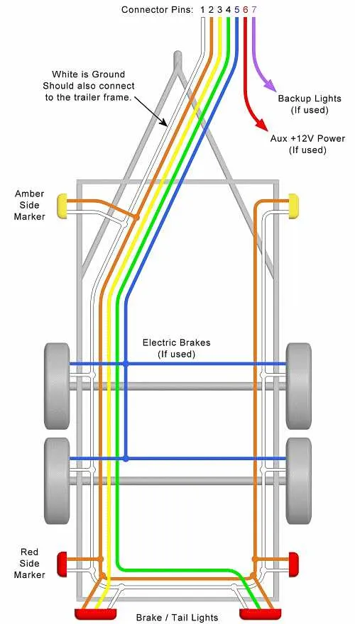
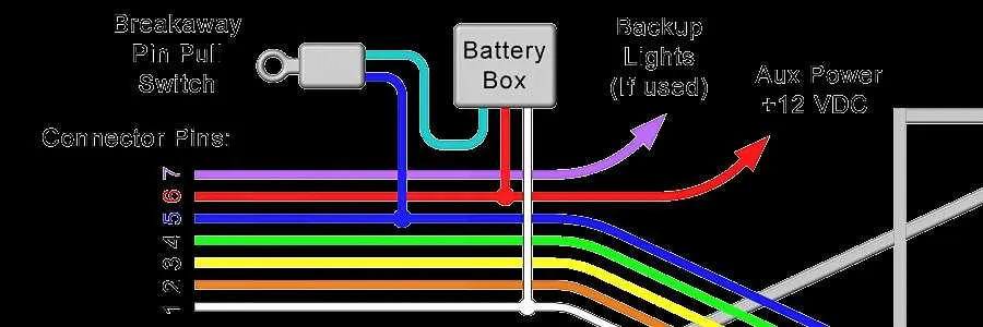
For proper integration of the electrical components in your towed unit, follow these steps: Ensure a secure link between the control system and the dedicated connectors, typically found at the rear of the towing vehicle. The red wire is usually assigned for the activation of the electronic system, while the black wire should be routed to the power source. The white wire plays a key role in providing grounding for the electrical network, ensuring a stable flow.
In addition, a dedicated wire for monitoring signals should be placed for the operational function that requires immediate attention when activated. This includes a clear and effective system that allows the towing vehicle to communicate with the towed unit efficiently. Utilize high-quality connectors to ensure proper conductivity, and avoid any interference from external factors like weather or vibrations.
Always use a fuse or circuit breaker for protection, which can prevent system overload and safeguard against potential malfunctions. Be sure to check all connections for firm installation before operating the system, as loose connections can result in ineffective performance.
Understanding the Components of Trailer Brake Wiring

To ensure proper functionality of the system, it is crucial to recognize and connect the right components. Here’s an overview of key elements involved:
- Power Supply: The source providing electrical energy to activate the system. It connects to the vehicle’s battery and ensures voltage reaches necessary components.
- Controller: This device is responsible for managing the force and timing applied to the wheels. It interfaces between the vehicle’s system and the connected unit.
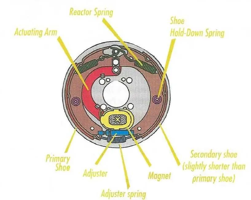
- Electromagnetic Coil: Positioned in the wheel assembly, this component generates a magnetic field to apply the braking force when current passes through it.
- Ground Connections: Ensure a complete circuit, grounding excess voltage and preventing electrical surges that could damage components.
- Fuses: Serve as protective elements that cut off power in case of short circuits, preventing system overloads.
- Connectors: The physical connectors play a crucial role in linking the different parts. They ensure secure, reliable connections that maintain system integrity.
- Relays: These devices manage the flow of electricity, ensuring that signals are directed properly to the electromagnetic coil when necessary.
- Switches: Operate the system manually or automatically, depending on the type, enabling the user to control the activation of the mechanisms.
Understanding each part helps in troubleshooting, installation, and maintenance, ensuring efficient performance over time.
Step-by-Step Guide to Connecting the Braking System
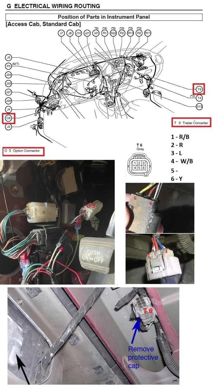
Start by ensuring your vehicle’s electrical system is compatible with the load controller and signal connections. Begin with the main power source, typically a 12V outlet from your car, which should be connected to a fuse box for overload protection. This will ensure your equipment is safeguarded from power surges.
Next, run the wire from the power source to the control unit located inside the cabin of your towing vehicle. Attach the signal wire from the unit to the controller for signal distribution to the wheels. Make sure the connections are properly insulated to avoid short circuits.
For the wheels, install the magnetic hubs or sensors to the axle. Secure the wiring to each unit with corrosion-resistant connectors and ensure the system is grounded to prevent electrical issues. Ensure all parts are securely attached and free from potential friction points that could damage the cables over time.
Test the functionality of the braking mechanism after all connections are made. When you activate the system, it should send signals to the individual hubs, engaging them evenly without delay or irregularities.
If you encounter any malfunctions, check the grounding and ensure the connections are tight. Recheck the signal flow to confirm no breakage or interruptions in the circuit. Make sure that each wheel is receiving proper power, and calibrate the unit if necessary to achieve proper engagement.
Troubleshooting Common Issues in Trailer Brake Wiring

If the system is unresponsive, begin by checking the connections at both ends of the vehicle harness. Loose or corroded connectors often lead to intermittent or total failure. Make sure the pins are free of dirt, rust, or damage, and that the wires are tightly secured. If necessary, clean or replace connectors.
Power failure can result from a blown fuse or malfunctioning controller. Check the fuse box and inspect for any blown fuses, replacing them with the correct amperage. Additionally, verify that the controller is receiving power from the tow vehicle. A faulty controller may need to be reset or replaced.
For inconsistent performance, check the continuity of the cables. Use a multimeter to test for any breaks or frays that could cause power loss. If a specific cable is damaged, cut out the damaged section and reconnect the wires properly using crimps or connectors designed for outdoor use.
If uneven activation occurs, inspect the voltage levels being sent to the axle units. These can be affected by faulty ground connections or poor routing of wires. Ensure that all ground points are clean and making solid contact with bare metal, free of paint or corrosion.
Overheating is often caused by too much current being drawn through the system, which could be due to undersized wiring or excessive load. Check that the wiring gauge is appropriate for the power requirements of the system. If in doubt, consult manufacturer specifications for wire size recommendations.
For a system that remains fully inactive despite proper power, the issue could lie in the relay. Test the relay by applying direct voltage and checking for response. If it fails to activate, replacing it with a new relay should resolve the issue.