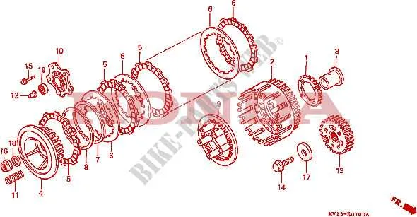
For precise maintenance or upgrades on the control system of the dual-cylinder off-road bike, use a comprehensive schematic of the steering assembly wiring. This blueprint provides exact locations and connections for switches, throttle, brake controls, and electronic components integrated into the front cockpit setup.
Refer to the color-coded wiring paths to quickly identify each circuit, ensuring accurate troubleshooting without guesswork. This resource highlights pin configurations on the connector plugs and the routing of cables through the frame to prevent damage during operation.
Utilizing this map optimizes repair efficiency by clearly distinguishing signals for lighting, ignition, and handle-operated functions. Proper adherence to this layout minimizes risks of electrical faults or control malfunctions, keeping the vehicle ready for demanding terrain.
Control Bar Wiring and Component Layout for the CRF1000L Model
For proper assembly and troubleshooting of the control lever system on the CRF1000L, follow these precise instructions:
- Throttle and Clutch Cables: Route both cables along the left and right sides of the steering column, securing with factory clamps to avoid interference with steering motion.
- Electrical Connectors: Position the switchgear plugs near the central wiring harness junction, ensuring no tension or sharp bends.
- Brake Fluid Reservoir: Mount on the right side, above the grip, with the hose running directly down to the front brake caliper for efficient fluid flow.
- Switch Assembly: Confirm the left switch cluster incorporates the high/low beam selector, horn button, and turn signal toggle with clear wiring paths to prevent shorts.
- Grip Heaters (if equipped): Connect power leads through the designated fuse box section, following the color-coded wiring schematic for optimal safety.
Additional wiring tips:
- Use dielectric grease on all connectors to prevent corrosion.
- Secure wires with zip ties at intervals of no more than 10 cm to reduce vibration damage.
- Verify all ground connections on the control bar to avoid electrical malfunctions.
Adhering strictly to the original schematic of the CRF1000L’s front control system ensures functionality and longevity of all integrated elements.
Interpreting Wiring Connections on the Adventure Bike’s Control Assembly Schematic
Focus first on color-coded lines to identify circuits: red typically signals power input, black grounds, and green or blue denote signal or accessory wiring. Confirm terminal labels such as IGN (ignition), ACC (accessory), and GND (ground) to match connection points accurately.
Trace each wire from switches to corresponding components–starter relay, horn, lighting, and kill switch–to ensure continuity and correct routing. Use the schematic’s numeric codes to verify pin assignments on connectors, avoiding cross-wiring.
Check for inline connectors or junctions marked on the map; these often indicate removable plugs critical for troubleshooting or replacements. Note the presence of fused lines, usually highlighted, which protect key circuits and must remain intact.
Identify common faults by comparing the schematic’s wire thickness indicators with actual cables; thinner wires handle signal transmission, thicker ones carry high current. Misinterpretation here can cause malfunction or damage.
Always verify the schematic version corresponds with the model year to prevent mismatches in connector layouts and wire colors, as updates affect component compatibility and function.
Identifying Switch Functions and Their Locations on the Control Bar
Left side controls: The clutch lever is accompanied by the high/low beam selector switch positioned above the turn signal toggle. Just below, you’ll find the horn button easily accessible with the thumb. The emergency kill switch is typically located on the upper right corner of this cluster for quick engine cutoff.
Right side controls: The throttle grip integrates the starter button immediately below it. Adjacent to this is the mode selector switch that allows toggling between different ride settings. The front brake lever is mounted here, with no additional buttons obstructing its operation.
Additional notes: Each switch is designed for intuitive thumb or index finger use without releasing the grip. The signal switch returns automatically to center after activation, while the mode selector requires a firm press to avoid accidental changes. Familiarizing yourself with these placements enhances control and safety during rides.
Troubleshooting Common Electrical Issues Using the Control Bar Schematic
Start by verifying continuity across the main wiring connectors related to the front control assembly. Use a multimeter to check each switch contact for proper operation, especially the ignition kill switch and starter button circuits, which often cause failure to start.
Inspect the wiring harness for visible damage or corrosion at junction points near the steering column. Pinpoint any broken or loose wires by referencing the schematic layout, focusing on the color codes and terminal locations for the front controls.
For intermittent signal loss, isolate the wiring section between the main fuse box and the left-hand controls. Test each circuit path individually, as faulty grounds or shorts in this area are common causes of erratic electrical behavior.
Check the front lighting controls by tracing the circuit from the battery through the switch connectors to the bulbs. Ensure all switch terminals are clean and firmly seated, and verify the presence of voltage under load conditions to rule out faulty switches or wiring breaks.
If indicators or horn fail, confirm the proper routing and connection of the auxiliary control wires shown in the schematic. Replace damaged connectors with OEM-style terminals to maintain circuit integrity and avoid resistance issues that cause partial failures.
Use the control unit schematic to identify and test inline fuses and relays associated with the front assembly. Replace any components that show signs of overheating or corrosion, as these directly impact electrical performance in the handlebar area.