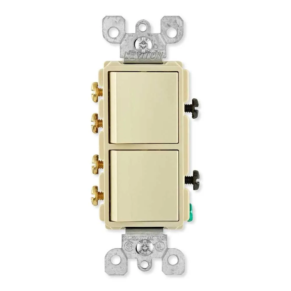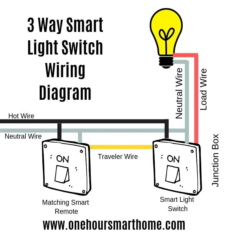
For a reliable and safe installation of a two-way control setup, begin by identifying the terminals on each device. The common terminal on one of the units should connect to the power supply, while the traveler terminals on both units should interconnect. It’s essential to use high-quality connectors and ensure all wires are tightly secured.
In addition, the ground wire must be properly connected to both units, ensuring safety in case of a malfunction. The hot wire from the power source should be routed to the common terminal of the first unit. Afterward, the remaining wire will continue to the second unit’s common terminal, completing the circuit.
When routing the wiring, make sure to follow the local electrical codes, particularly regarding the proper wire gauge and insulation ratings. This minimizes potential hazards and ensures the long-term stability of the setup. Verify continuity before completing the installation to guarantee all connections are correct and functioning.
Testing your work involves turning the power back on and checking each position of the control devices. If everything functions as expected, the installation is complete. If issues arise, double-check the connections and make sure no wires are loose or incorrectly placed.
Correct Installation for 3-Wire Electrical Circuits
Ensure that you connect the traveler and common terminals properly for optimal performance. Below is the step-by-step guide for setting up a 3-way configuration using the correct components.
- Terminal 1 (Common): Attach the black (hot) wire coming from the power source to this terminal on the first device.
- Traveler Terminals: On both devices, the traveler terminals should receive two wires (typically red and black) that link them together, allowing current to flow between the devices.
- Ground Connection: Connect the ground wire (bare or green) to the ground screw on both units, ensuring a safe pathway for any fault current.
- Power to Light: On the second device, attach the common terminal to the wire running to the light fixture. This connection completes the circuit and controls the light’s function.
Test all connections for proper continuity using a multimeter before securing the assembly inside the electrical box. If the connections are not accurate, the circuit will fail to operate correctly, resulting in a malfunction or safety hazard.
- Tools Needed: Wire strippers, screwdriver, electrical tester, wire nuts
- Safety Note: Always turn off the main power supply before beginning installation to avoid electrical shock.
Once completed, double-check the wiring for correctness, ensuring the switches will correctly toggle between light on and off at either position.
How to Connect a 3-Way Control for Basic Circuit Management

Begin by ensuring the power is off at the breaker panel before proceeding with any electrical work. Identify the traveler and common terminals on your device; the common terminal is where the hot wire from the power source connects, while the traveler terminals will connect to the wires running between the devices. Next, connect the black wire from the power source to the common terminal on your first device.
For the second device, attach the traveler wires to the traveler terminals. These are typically colored red and black. The common terminal on the second device will connect to the wire leading to the load (light fixture or outlet). Once the terminals are connected, secure the devices into their respective boxes, ensuring that the wires are not strained or pinched.
At the fixture, the hot wire from the power source should connect to the common terminal of the first device, while the neutral wire should go directly to the load. The traveler wires, which are responsible for signaling between the devices, should be connected to the respective terminals on both devices.
After completing the connections, test the circuit to ensure proper functionality. If the devices are wired correctly, they should allow control of the connected load from either location.
Understanding the Role of Traveler Wires in Multi-Control Electrical Configurations
The traveler wires are essential for enabling the control of a light from two separate locations. In a typical multi-control system, two devices are connected, with each providing a different input to the circuit. The traveler wires carry the current between these devices, allowing either one to complete or break the circuit, thereby turning the light on or off.
In such setups, you will often find two traveler terminals, one on each device. These terminals are used to connect the traveler wires. Each traveler wire serves as a conduit for electricity, transmitting power from one control to the other. When wiring, it’s critical to ensure that the traveler wires are connected to the correct terminals, as reversing them can result in improper functionality or even pose safety risks.
Traveler wires are typically color-coded (commonly black and red) to distinguish them from the ground and neutral wires. When troubleshooting or installing a multi-control system, always check that the traveler connections are secure and properly routed. A loose connection can cause intermittent power loss or failure to control the light from both locations.
By correctly implementing traveler wires, you create a seamless mechanism for alternating control over the connected light fixture, ensuring that both devices work harmoniously. Incorrect installation or wiring can disrupt the flow of electricity, leading to malfunction or complete failure of the system.
Common Mistakes to Avoid When Installing a 3-Wire Electrical System

Ensure proper connection of the traveler wires. Incorrectly connecting these wires can cause the circuit to malfunction, leaving the light inoperable or only partially functional. Verify that each traveler is connected to the right terminal in both devices.
Do not reverse the neutral and hot wires. This mistake can create a serious safety hazard and may lead to electrical shock or fires. Double-check that the hot wire is connected to the brass screw and the neutral to the silver screw in the proper location.
Avoid leaving any wire ends exposed. Strip only as much insulation as necessary to make a secure connection. Uncovered wire can cause short circuits or be a fire risk if it comes into contact with other surfaces.
Ensure that all connections are tight and secure. Loose connections can lead to arcing, which causes overheating and can damage the electrical components. Use a proper tool to tighten screws and check connections before finishing the installation.
Don’t forget to label wires during the disassembly phase. Mixing up wires from different circuits can make reinstallation difficult or impossible. Labeling the wires as you disconnect them helps you reconnect everything properly.
Check for ground connections. Failing to ground the system properly can cause serious safety risks, such as electrical shock. Ensure the ground wire is securely attached to the designated terminal.
Double-check the power is off before beginning work. Even experienced installers can make mistakes in identifying the correct breaker. Always test the circuit with a voltage tester to confirm the power is off.
Pay attention to the correct orientation of the devices. Installing the components in the wrong position can lead to confusion and malfunctions later on. Ensure that the marking on the device matches the expected position of the terminals.
Do not over-tighten screws. Over-tightening can damage the internal mechanism of the device, leading to malfunction or a broken connection. Tighten just enough to secure the wire, without excessive force.