If you’re facing electrical issues in your vehicle, understanding the configuration of the main power distribution system is crucial for troubleshooting. Start by checking the key connection points, as these are the most common culprits behind power loss or malfunctioning components. These areas contain several circuits responsible for controlling lights, accessories, and critical engine functions.
To efficiently diagnose any electrical faults, locate the primary relay and breaker setup, usually positioned near the driver’s side under the dashboard or in the engine compartment. These units house essential connections that are responsible for various vehicle systems, such as air conditioning, windshield wipers, and the ignition system. Ensure that all connections are secure and check for any visible signs of wear or corrosion.
Understanding the exact placement and function of each terminal and fuse will save you time when replacing components. Refer to the specific layout that corresponds to your model, as variations in design can impact the location and functionality of each circuit. It’s also helpful to familiarize yourself with the amperage ratings of each fuse to avoid overloading or incorrect replacements.
Tip: Keep a printed copy of the electrical layout in your glove compartment for quick reference during repairs. Be sure to disconnect the battery before working on the electrical system to prevent accidental short circuits.
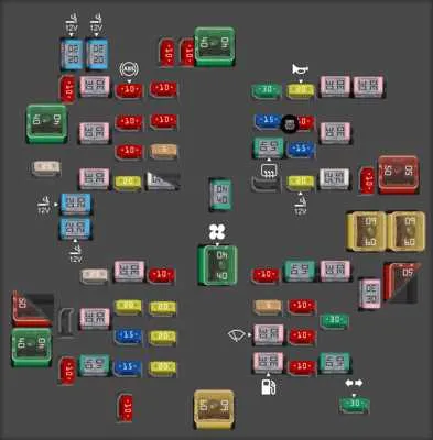
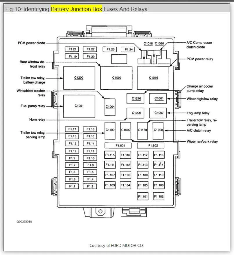
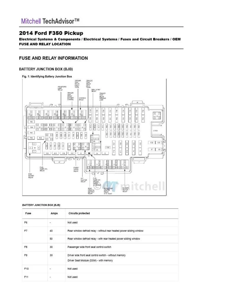
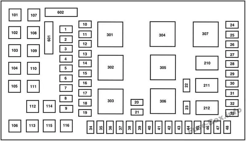
Electrical Component Layout for the 2004 F350

To ensure the proper functioning of your vehicle’s electrical system, it’s crucial to familiarize yourself with the location and function of each circuit in the control unit. Here’s a comprehensive guide to the various components found in the key electrical distribution system of your truck.
For the main unit near the driver’s side footwell, refer to the following common placement of circuits:
- Relay for ignition system: Found in slot 1, this relay is responsible for sending current to the ignition circuit.
- Headlight circuit: Located in slot 4, ensuring proper power flow to your vehicle’s front lights.
- Airbag control: Securely placed in slot 8, this controls the deployment system for safety features.
- ABS sensor: Found in slot 11, monitoring the anti-lock braking system.
- Power window motors: Slot 13, delivering power to both the driver and passenger side windows.
For another set of controls, usually near the engine bay, inspect the arrangement for:
- Engine control module: Found in slot 2, directly influencing key engine components and diagnostics.
- Cooling fan circuit: This crucial circuit, in slot 6, keeps your engine at an optimal temperature during operation.
- Fuel pump relay: Situated in slot 9, supplying power to the fuel delivery system.
- Transmission control: In slot 10, essential for automatic transmission function.
Refer to this layout when troubleshooting or replacing electrical parts. Always double-check the connections before inserting any replacement relays or fuses to avoid potential damage to the system.
Understanding the Layout and Location of Electrical Components
For optimal maintenance, always start by locating the primary distribution block under the dashboard on the driver’s side. This block controls most of the critical systems, such as lighting, HVAC, and interior electronics. For systems located in the engine bay, there is a secondary distribution unit near the battery compartment, responsible for engine management and cooling fan circuits.
Inside the interior module, fuses are arranged in two rows for better organization, with a cover that lists all the functions. The upper row generally handles high-priority elements, like airbags and power windows, while the lower row is dedicated to accessories like wipers and auxiliary power sockets.
If you’re troubleshooting, check the corresponding relay or fuse in the secondary unit when dealing with engine-related issues. For cabin issues, inspect the front row of the interior unit. A common issue is a blown connector for the radio or climate controls, so be sure to check the mid-section first if you experience failures in these areas.
Remember to refer to the cover’s guide to verify the specific amperage requirements for each component. Always replace with the same rating to avoid damage to wiring or circuits. If a component fails frequently, consider investigating possible short circuits or faulty modules instead of repeatedly replacing the fuse.
Identifying Key Fuses and Their Functions

Ensure you check the 30A circuit breaker for the electronic control system; it’s crucial for engine management. This will protect the wiring related to the main ECU. The 10A unit for the headlights should also be inspected to ensure optimal lighting during night driving. Additionally, the 15A link for the power windows will prevent any disruption in automatic window adjustments. If your air conditioning is malfunctioning, the 30A item dedicated to the blower motor must be checked to guarantee smooth airflow. For audio systems, locate the 5A component, as it is responsible for sound output. Always verify the 20A element that manages the brake lights–failure here could lead to safety issues. Finally, don’t forget the 40A protection associated with the fuel pump relay–without this, the engine won’t run efficiently.
Troubleshooting Common Electrical Issues in the 2004 F350 System

To quickly address electrical problems, always begin by checking the connections. Loose or corroded terminals can cause intermittent issues that are hard to diagnose. Follow these steps to resolve frequent malfunctions:
- Check for blown circuits: Inspect the specific areas known to fail, such as lighting, AC, or accessory power. A malfunctioning component is usually the root cause of power loss in these areas.
- Test the relay functionality: Verify that the relays are operating correctly. Faulty relays can cause various systems to stop working or become erratic.
- Inspect the power distribution system: Examine the main terminal for any signs of damage or wear. Often, issues can be traced back to poor connections between the battery and the distribution system.
- Look for burnt connectors: Heat buildup can cause certain connections to melt or burn. If you notice discolored areas on the wires or connectors, these need immediate replacement to avoid further damage.
Pay particular attention to specific sections that are known to suffer from corrosion, especially near moisture-prone areas. Corrosion can prevent proper current flow, leading to power interruptions or shorts.
- Fuse location: Certain systems rely on fuses placed in hard-to-reach spots, so ensure that all components are checked for proper functionality.
- Component testing: Use a multimeter to test individual circuits for continuity. If there is no continuity, further inspection may be required for wiring damage or faulty components.
By taking these steps, you’ll be able to quickly diagnose and fix most electrical issues without the need for professional help. It’s crucial to identify the problem area early to prevent unnecessary damage to the system.