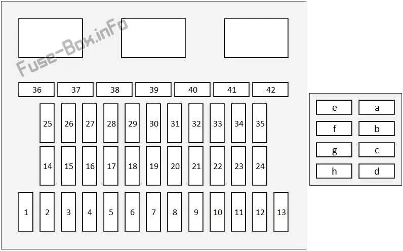
If you’re experiencing electrical issues with your vehicle, it’s essential to have a clear understanding of the distribution system that connects power to various components. The layout of the power distribution components is crucial for diagnosing malfunctions or replacing blown circuits. Knowing the exact locations and functions of each element within this system will help you avoid unnecessary repairs and ensure efficient troubleshooting.
Start by identifying the main distribution panel that houses the critical fuses. This will typically be located either inside the cabin or within the engine bay. Pay attention to the color coding and labeling, which indicates the amperage and purpose of each connection. You may find multiple panels, each designed to protect specific electrical systems like lighting, power windows, or air conditioning.
When dealing with issues, always consult the markings that correspond to each fuse or relay. These identifiers will provide clear instructions on how to approach repairs or replacements. Use manufacturer-specific guides to ensure you’re using the right components and maintaining the system’s integrity.
For greater accuracy, check the vehicle’s manual for detailed maps that outline the layout of these components. This information can save you time and prevent unnecessary mistakes when handling electrical system components.
Fuse and Relay Locations in the 2016 Model
For proper troubleshooting and fuse replacement, it is essential to understand the correct positioning of electrical components within the vehicle. Below are the key areas where the protective components are located:
- Under the hood near the engine bay: This section contains the primary relays for engine management and other high-current systems.
- Inside the cabin, below the dashboard: A compact unit here manages circuits for interior systems such as lights, audio, and HVAC.
Check these spots to locate the correct fuses for specific functions:
- Engine management and sensors: Commonly found in the engine compartment section.
- Interior comfort systems: Typically in the dashboard area or near the driver’s side footwell.
- Lighting and power outlets: These are usually in the cabin fuse assembly.
If a specific system is not working, inspect the corresponding area and replace any blown units with the appropriate amperage rating. Always refer to the vehicle’s user manual for exact specifications and safe procedures during maintenance.
Identifying Fuse Locations in the 2016 Honda Accord

For effective troubleshooting, locate the electrical component panel under the dashboard near the driver’s side. The most common spots for circuit protection devices include this area, as well as near the engine compartment. Always consult the owner’s manual for precise location and identification details.
In the interior, the central area often holds devices for essential systems, such as lights, infotainment, and climate control. Under the hood, the components for the engine and powertrain systems are usually housed in the more accessible areas for easier maintenance.
To avoid errors, ensure you’re referencing the right schematic before proceeding with any replacements. Using the correct tools will minimize the risk of further damage. Once located, check the state of each element by visual inspection or using a multimeter for more accurate diagnostics.
How to Replace a Fuse in the Honda Accord
Start by turning off the ignition and removing the key to prevent electrical shorts. Use a flashlight to locate the under-dash panel on the driver’s side or the auxiliary compartment near the engine bay. Remove the cover and check the chart on the reverse side to identify the exact slot related to the malfunctioning component.
Inspect each element visually or with a multimeter. A broken filament or lack of continuity confirms the issue. Use plastic tweezers to extract the damaged unit without disturbing adjacent circuits. Match the amperage rating exactly–typically labeled in white numbers like 10A or 15A–and never substitute with a higher value.
Insert the new piece securely until it clicks into place. Reattach the protective lid and turn the vehicle back on to verify function. Always store a few spare pieces of different ratings in the glove compartment for future repairs.
Troubleshooting Common Electrical Panel Issues
Begin by checking the relay labeled “IG1” using a multimeter set to continuity mode. If there is no signal when the ignition is on, the component may be defective or its socket corroded.
Inspect the slot marked “ACC” for signs of overheating–melted plastic or burnt odor often indicates a short circuit downstream, usually within the accessory wiring harness.
If your power windows or radio are unresponsive, verify the integrity of the 20A thermal link in the driver’s side interior module. Replace only with a matching amperage rating to avoid overloading.
For engine starting issues, probe the cavity assigned to the starter relay. Voltage should be present on the input terminal when the key is turned to “START.” If absent, test upstream wiring and ignition switch output.
Do not overlook the under-hood junction block. The 30A slot marked “Main” often protects critical ECM functions. Loss of continuity here may disable fuel injection or ignition systems entirely.
Corrosion is common in weather-exposed compartments. Detach the connectors one by one and clean with contact spray. Avoid dielectric grease in high-current paths–it may increase resistance under load.
Always reconnect the battery only after all inspections and replacements are complete to avoid false positives or secondary damage from surges.