If you’re tackling electrical setups in GM vehicles, start by focusing on understanding the fundamental connections. The key is to break down each component into its role and figure out how they link to one another. Pay attention to common features like the ignition system, lighting, and power supply circuits.
Begin with the basics: Identify the core elements such as the battery, fuse box, and control units. These are the main sources of energy distribution, and knowing how they interact with the rest of the system will simplify troubleshooting.
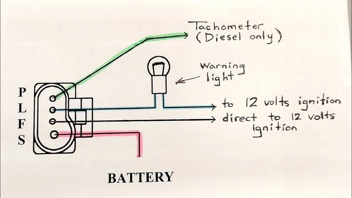
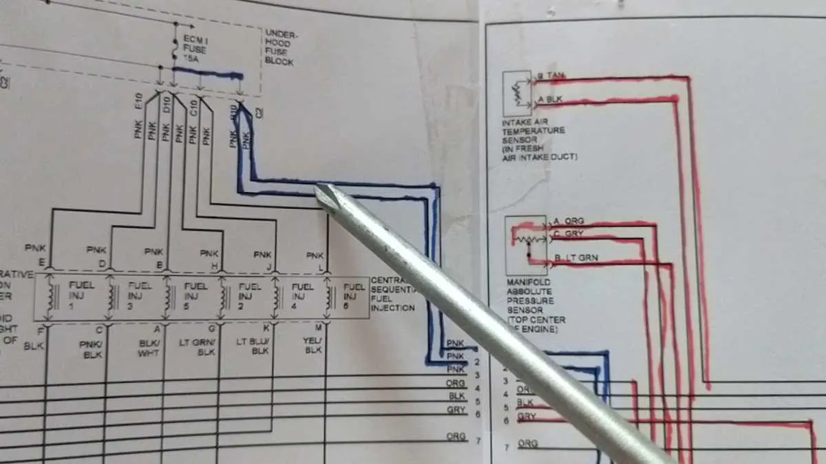
Use reference materials: Reliable sources, such as service manuals, often contain clear details of pinouts and connections. These documents will help you visualize how the systems are arranged, providing you with the exact locations of terminals and connectors, saving time when identifying problems.
Focus on troubleshooting: Check for common issues like short circuits, blown fuses, or damaged components. Test each part with a multimeter to ensure proper voltage is being delivered to each section. Understanding voltage flow is essential for pinpointing faults.
Always double-check your work before proceeding to ensure all connections are correct and secure. This will prevent unexpected malfunctions and make maintenance easier in the future.
GM Electrical Schematics Breakdown
Start with identifying the main power sources, such as the battery and alternator, and trace their connections to the fuse box. Ensure all connections are securely fastened, as any loose terminals can cause intermittent electrical issues.
Pay attention to the color codes used in the vehicle’s harness. For example, red wires typically indicate power, while black or brown wires are used for grounding. Make sure to cross-check these color codes with the model year of the vehicle, as GM may have made adjustments over time.
When inspecting switches, relays, and connectors, always use a multimeter to verify continuity. If a component is not responding as expected, test it for power supply first, and then check for continuity across the switches or relays.
For advanced troubleshooting, focus on areas like the ignition system and fuse allocation. Faults in these areas often disrupt the entire electrical system, causing unexpected shutdowns or malfunctioning components. Understanding which circuits are interconnected will allow you to narrow down the problem quickly.
In case of any short circuit or blown fuses, check for pinched or damaged wires that could have caused the issue. This is especially true near moving parts like the steering column or under the dashboard where wires are prone to wear and tear.
Lastly, always ensure proper grounding of every component. Poor ground connections are a common source of electrical malfunctions and can be overlooked during repairs.
Understanding Common GM Wiring Colors and Codes

GM uses specific color codes to identify functions of their electrical systems. Here are the most common color codes and their meanings:
Black: Typically signifies a ground connection. Always check for continuity to ensure proper grounding.
Red: Indicates a constant power source. Red wires are often connected to the battery, supplying power when the car is on or off.
Pink: Used for switched power, typically activated when the ignition is turned on. These are important for devices that need power only when the engine is running.
Blue: Often found in connections related to accessories or relays. In some cases, it is used for the signal to the fuel pump.
Yellow: Commonly associated with lighting circuits, such as headlights or interior lights.
Green: Generally used for sensors, such as those related to the cooling system or the oxygen sensor.
White: Represents a neutral or return path in certain systems. White wires are also commonly used for interior lighting and speaker connections.
Brown: Typically used in circuits requiring variable power, such as those controlling fan speeds or seat adjustments.
Gray: Often related to interior lighting and sometimes used for the backlighting of dashboard instruments.
Understanding these color codes is crucial for troubleshooting electrical components in GM vehicles. Always use a multimeter to verify the function of each connection before making modifications.
How to Trace Power and Ground Circuits in GM Vehicles
Start by locating the fuse box to identify the main power source. The fuse box is typically located under the dashboard or in the engine compartment. Check the fuses related to the system you’re troubleshooting, ensuring they’re intact and making good contact.
Next, use a multimeter to test voltage at key points in the system. Set your meter to DC voltage and check the input terminals of components for proper voltage. For power circuits, a reading close to the battery voltage (typically 12-14V) indicates the circuit is functioning. If there is no voltage, trace the path back to the fuse box and verify continuity.
For ground circuits, connect the negative probe of your meter to a known good ground, then test the ground terminal of the component. A reading of zero volts indicates a solid connection. If the ground is faulty, you may encounter a high resistance or voltage reading.
When tracing, follow the wiring harnesses carefully. Often, the power and ground wires run parallel to one another and may share common connectors. Look for any damaged, corroded, or disconnected wires. Inspect connectors for corrosion or loose connections, which are common culprits in GM vehicles.
If you suspect a ground issue, verify the ground points at the engine block or chassis. A bad ground can cause erratic behavior in electrical components. Always clean ground connections before proceeding with further tests.
Additionally, use GM-specific service manuals or reference materials to verify pinouts and connector types for particular systems. The correct approach to tracing circuits can vary depending on the year, model, and system you’re working with.
Diagnosing Electrical Issues Using GM Schematics

To troubleshoot electrical faults, start by identifying the component or circuit causing the issue. Follow these key steps:
- Locate the Power Source – Always begin by checking the fuse box and relays. Use the power flow indicators to ensure proper current distribution.
- Trace the Path – Map out the exact route the electrical current follows. Identify where connections should be made, and look for potential interruptions.
- Test Continuity – Use a multimeter to measure continuity. Start from the power source and work your way through each connection. If the circuit shows no continuity, you’ve found the break.
- Inspect Grounding Points – A poor or loose ground can cause various electrical malfunctions. Check grounding connections along the traced route.
- Check Components Individually – If power and grounds are fine, the issue might lie with specific components. Check switches, sensors, and connectors for signs of damage or wear.
Ensure you cross-reference the outlined steps with the electrical flow and component layout specific to the GM system you’re working with.
- Look for Short Circuits – Overheating or blown fuses are often signs of shorts. Follow any potential short paths by carefully reviewing the flow paths for damaged insulation.
- Verify Connections – Loose or corroded terminals can cause intermittent power loss. Inspect each connector closely.
Keep the service manual or reference material handy to confirm the correct order and values for every test. The most critical step is to focus on the actual system behavior rather than assuming common faults.