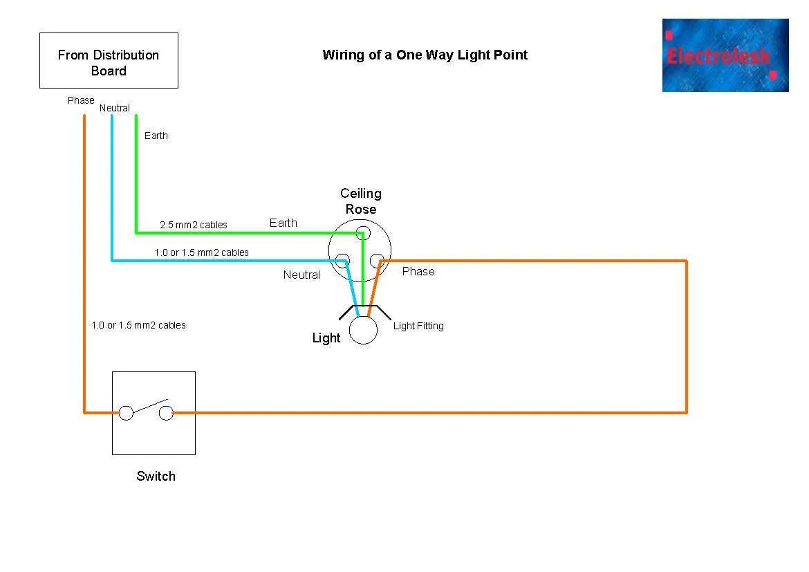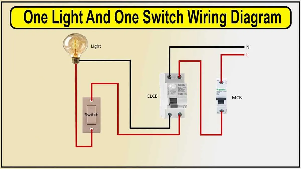
Use a single-pole controller for basic room illumination. Connect the phase wire to the upper terminal of the controller, then route the output to the hot terminal of the fixture. The neutral line goes directly from the panel to the fixture. Grounding must be continuous and bonded to the controller’s metal box, if present.
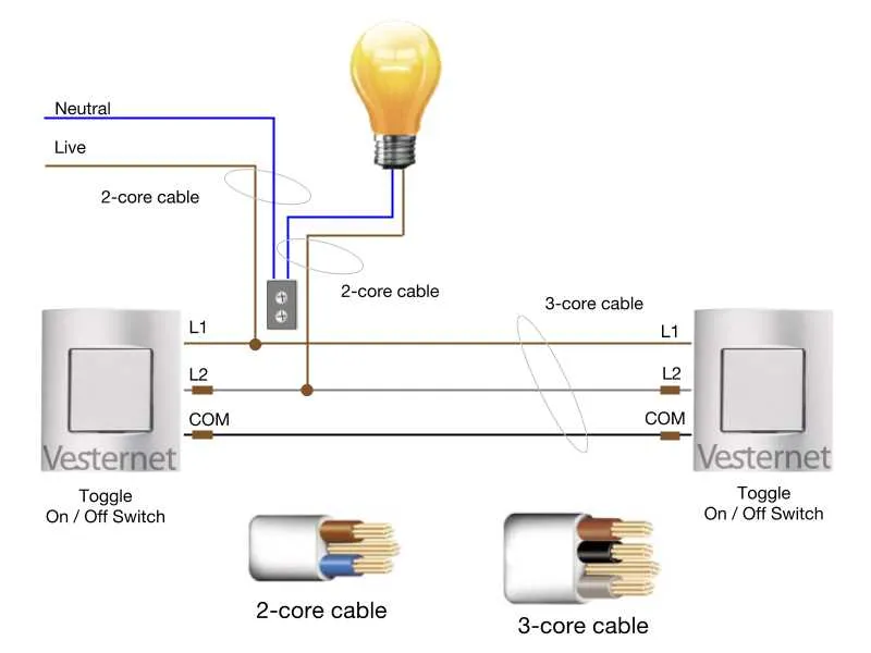
For staircases or hallways, install a pair of three-way units. Power enters through the first device, passes to the traveler wires, and exits at the second unit toward the bulb. The common terminals are critical: one receives power, the other connects to the fixture. Travelers link both units using 14/3 cable–black, red, and white (used as neutral or second traveler, depending on code).
If wall space is limited, consider a push-button controller with a relay module placed in the ceiling box. Low-voltage wiring connects the button to the relay, which switches the mains voltage. This setup reduces wall clutter while maintaining full functionality.
Never route traveler wires through different raceways. All conductors must share the same conduit to prevent magnetic field imbalance and meet code requirements. Test continuity and voltage before energizing. Use a non-contact tester to verify load presence after installation.
Wiring Layout for Wall-Controlled Illumination
Start by identifying the hot wire from the power source–usually black–entering the outlet box. Connect it to the terminal marked “common” on the controller unit. This is critical for single-pole configurations.
Next, route the traveler wire–typically red or black–to the ceiling fixture. Link it to the terminal marked “load” on the control unit. Confirm that the neutral wire (white) runs uninterrupted from the power source to the lamp holder.
For grounded circuits, attach the bare or green wire to both the metal box (if applicable) and the grounding screw on the control device. Skip this step only if the enclosure is plastic and floating.
Verify connections with a voltage tester before restoring power. Ensure that no exposed copper is visible outside wire nuts and that all terminals are firmly secured.
In 3-way setups, identify the common wire in both boxes using a multimeter. Attach it to the black terminal on each controller. Travelers–often red and black–go to the remaining screws. The orientation must match on both ends to prevent malfunction.
Single-Pole Wiring: Step-by-Step Layout

Start by cutting off power at the circuit breaker. Confirm with a voltage tester before touching any conductors.
Use 14/2 NM cable (for 15A circuits) or 12/2 (for 20A). The black lead carries current from the panel to the controller. The white acts as the return path from the fixture.
Connect the black wire from the power source to one brass terminal. The black wire going to the ceiling unit connects to the second brass terminal. Use a needle-nose plier to form clockwise loops for secure connections.
The white conductors should bypass the controller entirely. Join them with a wire connector inside the box. Cap them properly to prevent arc faults.
The bare copper or green wire connects to the green grounding screw. Secure all connections with electrical tape, then fit the controller back into the box and fasten it.
Restore power and test the function using a tester at the fixture. If the bulb responds properly, installation is complete.
How to Identify Line and Load Wires in a Switch Box

Shut off power at the breaker before opening the wall box. Use a non-contact voltage tester to confirm no current is present.
Separate the wires carefully. Typically, the line conductor brings power from the panel and stays hot, while the load conductor runs to the controlled fixture.
Restore power briefly and test each wire with a voltage detector. The one showing voltage is the line. Turn off power again before continuing.
If multiple cables enter the box, trace each one. The line wire usually connects directly to the common terminal of the control device. The load wire often connects to the brass or traveler terminal depending on configuration.
Black wires are often hot, but do not rely on color alone. Use labeling tape to mark identified conductors for future reference.
In cases with pigtails, find the incoming feed by checking the wirenut bundles. The feed often joins with a short jumper to the control device’s terminal.
If uncertain, consult wiring diagrams for your specific circuit type or use a continuity tester with power off to verify destinations.
3-Way Wiring with Common Mistakes
Always verify that the traveler terminals are correctly identified before connecting conductors. Mislabeling leads to unpredictable behavior and safety hazards.
- Wrong terminal usage: Attaching the power feed to a traveler instead of the designated common point causes the circuit to fail intermittently.
- Neutral misrouting: Routing the neutral through one of the controlling units instead of directly to the load breaks continuity and violates electrical code.
- Ground omission: Neglecting to bond the ground wire across all control points introduces shock risk and fails inspection.
- Inconsistent wire color: Using identical hues for different roles (e.g., black for both power and travelers) leads to confusion during future maintenance.
- Load misplacement: Placing the fixture between two controls without proper jumper configuration results in incomplete circuits.
Use a continuity tester to confirm traveler paths and ensure the common terminal receives the hot or the load leg–never both. Maintain consistent labeling and document each connection for future reference.