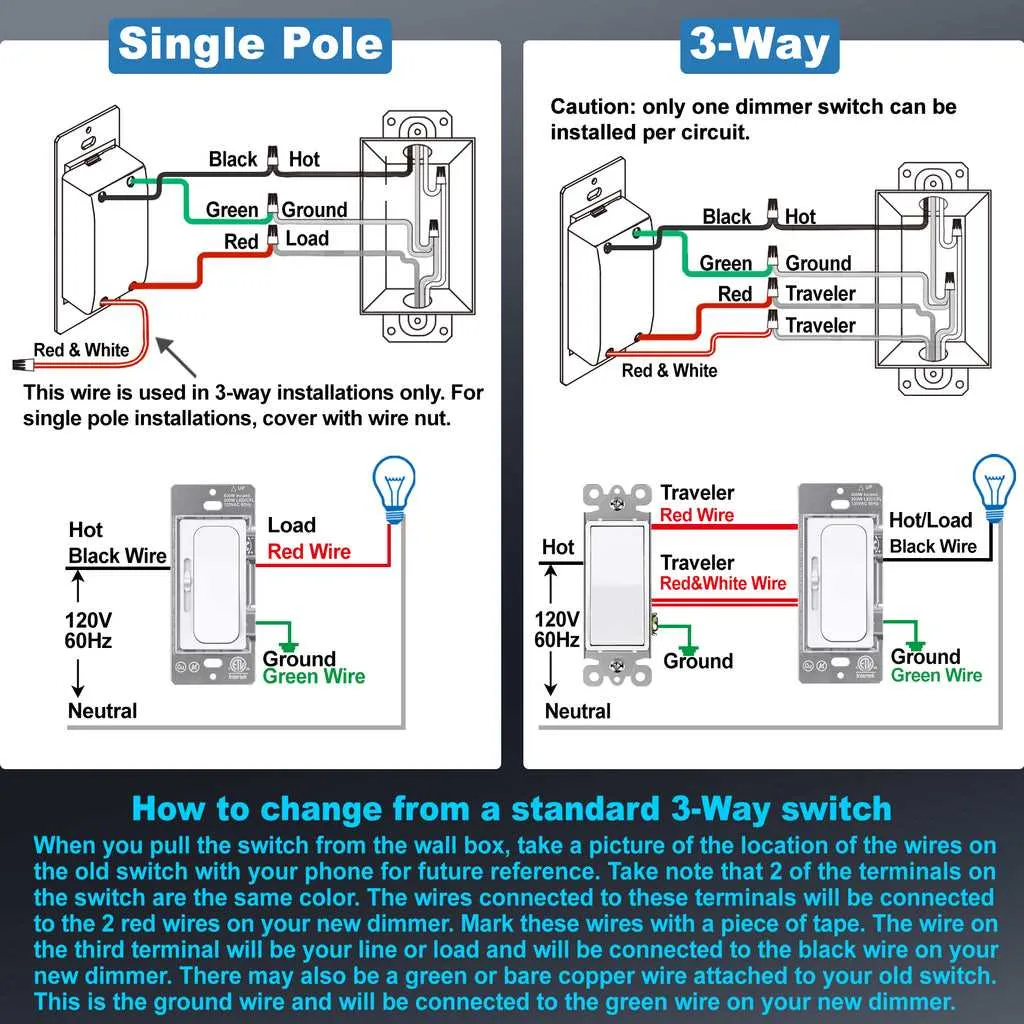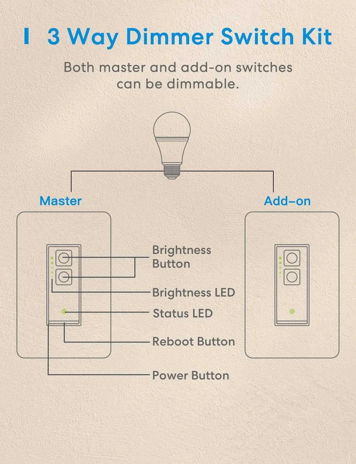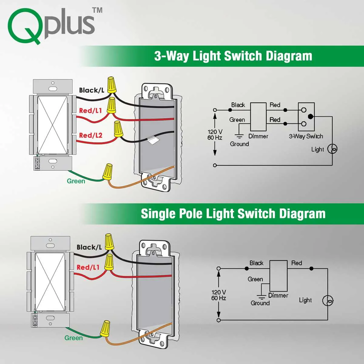
When installing a multi-location control for your home’s lighting system, it is essential to understand the specific wiring required to make the connection work. Typically, you’ll need two control points to regulate the power from different spots. This setup is especially useful for large rooms or staircases, where controlling the light from both ends simplifies usability.
Ensure that the primary unit connects to the electrical panel while the secondary unit serves as the remote control. The wiring configuration between the two locations should use a three-wire system, often referred to as a traveler wire, in addition to the standard live and neutral lines.
Start by connecting the live wire to the first unit, which will control the flow of electricity to the secondary control. The second unit will have a direct connection to the light fixture, enabling full operation from either position. The traveler wires play a crucial role in transmitting the switching signal between the controls.
Key Tip: Make sure both units are properly grounded for safety. Also, double-check the wiring diagram before proceeding to avoid incorrect connections, which could lead to electrical hazards. The correct configuration ensures smooth operation, allowing either control to manage the light source seamlessly.
Wiring Multiple Control Points for Adjustable Illumination
To control a single fixture from two different locations with variable brightness, follow this wiring configuration. The setup ensures seamless adjustment, enhancing the versatility of your electrical system.
- Use two standard electrical boxes for installation, ensuring proper spacing for each component.
- Install the primary control unit at the first location, where the incoming power supply connects.
- Run a three-wire cable between the two control boxes. This cable should include a neutral, a hot, and a traveler wire.
- The secondary unit must be placed at the second location, where the traveler and neutral wires terminate.
- Ensure the ground wire is securely connected to all components, avoiding any electrical hazards.
The key is to maintain consistent and correct connections to the hot, neutral, and traveler terminals at both ends. When using a variable control unit, confirm that the device is rated for your specific load to avoid malfunction.
For optimal performance, make sure that both units are rated for the same amperage and wattage. If you plan on adjusting the brightness frequently, choose a unit with a smooth, gradual response to changes.
Test the setup by operating both points to ensure smooth functionality. Any flickering or non-responsive behavior typically points to a loose wire or improper installation.
Wiring Instructions for a Dual-Control Lighting System

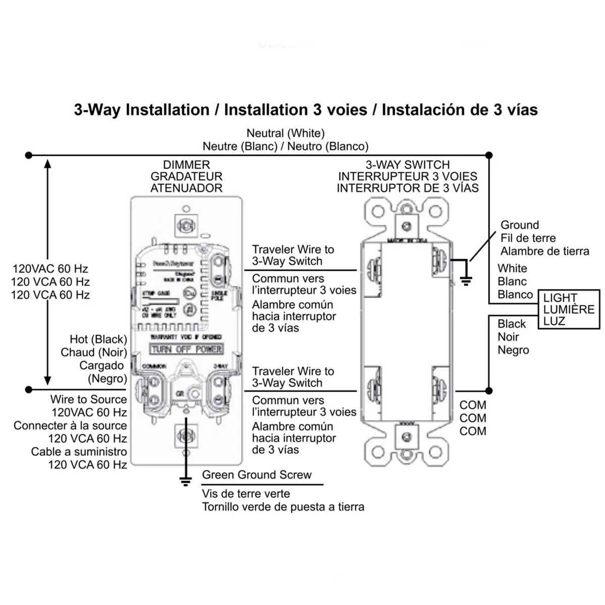
To successfully install a dual-control lighting system, connect the power source, control device, and fixture as follows. Begin by identifying the incoming power cable, which will connect to the first control unit. The live wire from the power supply should be attached to the terminal marked “Common” on the first unit.
Next, the traveler wires should be connected to the remaining two terminals on the first device. These will serve as the connection points for the traveler wires that extend to the second unit. The second control unit will also have corresponding terminals for the incoming traveler wires. Attach these wires to the appropriate terminals on the second device.
Finally, the load wire, which is responsible for carrying the current to the fixture, should be connected to the “Common” terminal on the second unit. Ensure that all connections are secure and insulated, then test the system by activating both units in various configurations to ensure proper functionality.
Ensure all connections follow the manufacturer’s wiring guide and meet local electrical codes for safety. This setup allows for controlling a fixture from two different locations with full control over the brightness level.
How to Install a 3-Control Adjustment Device in Your Home

To set up a dual-control fixture adjuster in a room, ensure the power is turned off at the breaker. You’ll need a tester to verify there’s no live current before proceeding. Replace the current unit by disconnecting the wires from the old control mechanism. Identify the two terminals for input power and load, then wire them to the corresponding points on the new unit according to manufacturer instructions.
Next, connect the traveler terminals between both adjusters, making sure the connections are secure and insulated. These are the points that allow control from either location. For the grounding wire, attach it to the designated ground screw on the device and secure it to the electrical box, ensuring no exposed wire is left visible.
Once everything is wired correctly, secure the unit into the electrical box and fasten the cover plate. Restore power to the circuit and test the operation of the new controls from both positions. If any issues arise, double-check the connections or consult a licensed electrician for assistance.
Common Troubleshooting Tips for 3-Way Light Dimmer Switches

Check the Wiring Connections: Ensure that all connections are tight and properly secured. Loose or improperly connected wires can cause flickering, failure to adjust brightness, or complete malfunction. Double-check the terminals and wire connections to make sure they match the manufacturer’s instructions.
Verify the Power Source: If the fixture is not responding, test the power at the source. If the power is cut off at the panel or fuse box, the mechanism won’t operate. Make sure the circuit is active and that no breakers have tripped.
Test the Compatibility: Not all bulbs work with every dimming mechanism. Check the bulb type and verify whether it’s compatible with your control unit. Incandescent bulbs are the most commonly supported, while LED and CFL options may require specific models or additional load resistors to function properly.
Inspect the Mechanism for Damage: Physical wear or electrical damage to the device can impair its performance. Check for signs of burning, discoloration, or other visible damage on the control unit. If you spot any issues, consider replacing the part.
Confirm Proper Grounding: Improper grounding can lead to erratic behavior or even hazards. Ensure that the grounding wire is correctly attached and making good contact with the grounding terminal.
Check for Interference: Certain devices like motors or heavy electronics can interfere with the signal from the control unit. Disconnect any non-essential appliances to see if performance improves. If so, try relocating sensitive equipment.
Reset the Unit: Some models may need to be reset if settings or configurations become disrupted. Follow the manufacturer’s guide for performing a reset or calibration of the device.
Test the Control with Another Fixture: If none of the previous steps resolve the issue, try installing the same control in a different fixture. If the issue persists, the unit may need replacing.