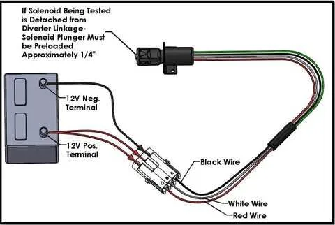
To properly connect a 3-lead electromagnetic device, ensure that the correct terminals are linked to the power source, ground, and control signal. The first terminal should be connected to the positive side of the power supply, while the second terminal should go to the negative side, completing the circuit. The third terminal typically receives the signal that controls the device’s activation or deactivation.
Power Source Integration: For efficient operation, the device must be connected to an appropriate voltage source based on its specifications. The power input needs to be stable to avoid damage to the components. Double-check the voltage rating of the system before proceeding with any connections.
Signal Control: The activation signal often comes from a relay or a microcontroller. It’s crucial to ensure that the signal is appropriately configured to match the device’s response requirement. A low-voltage or high-voltage input could determine whether the component is energized or remains in a dormant state.
Correct polarity is vital when establishing the ground connections. A reverse polarity may lead to malfunction or even permanent damage. Always ensure that the negative terminal is securely linked to the system’s ground or negative power rail.
3-Wire Control Circuit Setup

When dealing with a 3-wire setup for electric actuators, ensuring the correct sequence of connections is critical for proper operation. Here’s a step-by-step guide to help you establish the connections accurately:
- Power Source: The first terminal should be connected to the positive terminal of your power supply. Ensure the voltage matches the specifications of your device.
- Common Ground: The second terminal is the common or neutral connection. This should be linked to the ground or negative terminal of your power source. Double-check that this is securely connected to avoid malfunction.
- Control Line: The third connection is typically used for a switching mechanism, such as a relay or controller. This wire will control the activation and deactivation of the actuator. It should be connected to the switching component, which will complete the circuit when needed.
Ensure all connections are tightly secured and insulated to prevent short circuits or accidental disconnections. Test the system after installation to confirm that each part of the setup is functioning correctly.
If you’re using a relay or controller, ensure it’s rated for the current required by your system to avoid overloads or malfunctions. Use the correct gauge for each wire, and verify that the components are properly rated for the application.
Wiring Connections for 3-Wire Coil Control with Power Supply

For proper operation of the 3-wire coil, connect the terminal labeled “positive” to the 24V DC power source. The “negative” terminal should be linked to the ground or return path. The third terminal, used for controlling the activation, should be connected to the control signal, typically from a relay or switch that activates the device.
Ensure that the control circuit voltage matches the coil’s operating voltage to avoid damage. Verify that the power supply is correctly rated for the coil’s power consumption, ensuring stable and efficient performance.
In the case of a 24V DC coil, ensure a maximum current of 0.5A, with a tolerance for surge during activation. Use a fuse rated slightly above this current to protect against potential short circuits. Proper insulation and protection should be applied to all exposed conductive parts to avoid accidental contact.
Important: Double-check the polarity of all connections before powering up the system. Incorrect connections may result in malfunction or damage to the components.
How to Identify and Connect the Common, Coil, and Ground Wires
Identify the Common Connection: The common terminal is typically marked or identified by a specific color or symbol. It is often the central point where the power supply connects to the system. In most cases, this terminal is used as a reference for the other connections.
Determine the Coil Leads: The coil connections are responsible for activating the system when power is applied. One lead of the coil connects to the common terminal, while the other should go to the control or trigger circuit. Ensure that the coil is correctly oriented to prevent incorrect polarity issues.
Locate the Ground Terminal: The ground terminal completes the circuit by connecting to the negative side of the power source. It is critical to ensure the ground connection is securely fastened to prevent malfunctions or potential hazards. This is usually marked with a ground symbol (⏚) or may be directly connected to the chassis or frame in some setups.
Connection Tips: Always ensure that the common terminal is connected first, as this provides the basis for the other connections. When wiring the coil and ground, double-check that each connection follows the correct polarity to ensure proper functionality. Use a multimeter to verify continuity and proper grounding before powering up the system.
Testing and Troubleshooting 3 Wire Circuit Connections
Start by checking for power supply issues. Use a multimeter to verify that the voltage is within the specified range at the actuator’s terminals. If there’s no power, ensure the fuse or circuit breaker is intact, and inspect the power source for consistency.
Next, confirm the continuity of the control lines. Set your multimeter to continuity mode and check for any interruptions in the path. If the meter does not beep or show continuity, inspect connectors for damage, corrosion, or poor contact. Clean or replace any faulty components.
If the device doesn’t activate, test the current draw when the system is energized. The current should align with the manufacturer’s specifications. If it’s too high or low, the actuator might be malfunctioning, or there could be an issue with the load or control circuit.
Test the control switch or relay. If the signal is not being transmitted to the actuator, the switch may be defective. Check its functionality by measuring the control voltage when it’s activated. A defective relay may fail to complete the circuit, preventing activation.
Check for grounding problems. A poor ground connection can cause erratic behavior or complete failure. Use a multimeter to verify the ground potential is stable and there’s no excessive resistance between the grounding point and the system.
Finally, if troubleshooting doesn’t resolve the issue, replace suspect components and retest. Begin with the simplest elements, like connectors and the power source, before moving to more complex ones like the control unit or the actuator itself.