If you are looking to troubleshoot or modify the electrical setup of the windshield clearing system in a GM vehicle, it’s essential to understand the specific connections involved. Begin by identifying the power source and ground connections to ensure proper functionality of the system. The main feed typically comes from the fuse box, connecting directly to the control switch.
The next key component is the relay, which activates the clearing mechanism based on the user input. Ensure that the relay is receiving the correct signal from the switch and that it is correctly wired to the relevant actuator. The current flow must be uninterrupted, so double-check for any possible breaks in the circuit.
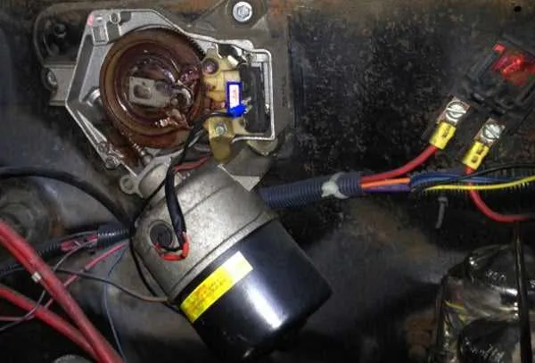
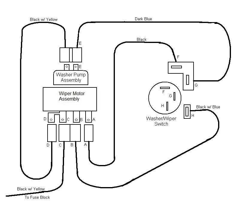
Additionally, focus on the connection to the actuator assembly, which is responsible for the movement. Pay attention to the color coding of the wires and their respective placement in the connector blocks. Any incorrect connection here can prevent the system from operating as expected. Use a multimeter to confirm voltage readings at different points to verify the setup.
To avoid malfunctions, inspect the entire harness for signs of wear, corrosion, or loose connections. Ensure that all grounds are securely fastened and free of rust or debris, as a poor ground connection is one of the most common causes of system failure.
GM Windshield Cleaner System Connection Layout

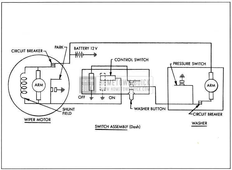
For optimal functionality, ensure the correct routing of power and ground cables to the windshield clearing assembly. The switch should connect directly to the central relay, while a separate fused line provides current to the assembly’s power input. Ground the component to the vehicle frame using a solid, corrosion-resistant connection to avoid electrical issues.
The input terminal from the switch will activate the relay when engaged, supplying current to the brush actuator. Pay attention to the continuity of connections, as a loose or corroded wire can cause intermittent failures. The relay itself should be rated to handle the current demands of the system; ensure it’s rated for at least 20A to prevent overheating or failure.
Verify that all connections are securely fastened with no frayed wires, especially in high-movement areas. Use high-quality connectors to minimize wear. It’s essential that the relay’s ground path be directly tied to the frame, not relying on any other components for a proper connection.
Test the system periodically to ensure there are no voltage drops, and always replace worn-out connectors or cables immediately. Ensure the fuse is rated for the correct amperage, typically 15 to 20 amps for most GM models, depending on year and type.
How to Identify Connections for GM Windshield Washer Components
Start by locating the connector with three to four pins, typically positioned near the device assembly. The color coding of the wires is crucial for identifying each function. On most GM vehicles, the ground wire is often black or brown. The power supply usually features a red or blue wire, while control signals might be in a light green or purple hue. The intermediate wire can be yellow or white, depending on the model.
Test for continuity to confirm that each wire is routed correctly. Use a multimeter to verify that the ground wire is properly connected to the vehicle chassis, ensuring a secure electrical return path. Check that the power wire delivers voltage when the switch is activated. A lack of voltage or inconsistent readings could indicate a faulty connection.
Trace each line from the connector to the control module to ensure no interruptions in the path. If any section of the circuit appears damaged or corroded, it’s essential to replace the affected components immediately. Inspect for any exposed copper or frayed insulation that may lead to short circuits, which could disrupt the functioning of the entire system.
In some cases, GM utilizes a relay for switching between different operational modes. If you encounter a separate relay, check that the activation signal and power input are intact, as these components directly influence the device’s performance.
Common Electrical Issues in GM Windshield Systems and How to Fix Them

When the clearing mechanism fails to operate properly, start by checking the power supply. Ensure the fuse is intact and not blown; a damaged fuse can completely stop functionality. Inspect the connections at the battery, switch, and relay for any signs of corrosion or loose connections, as poor contact can lead to inconsistent performance.
If there is no movement despite power being supplied, the issue may lie in the control switch or ground connection. A faulty switch can prevent the signal from reaching the motor, while a poor ground connection will hinder the return of current, causing the entire system to malfunction. Clean the contacts and verify that they are securely connected.
Inconsistent or slow movement typically indicates a problem with the internal components of the system, such as brushes or the armature. In this case, the unit may need to be disassembled for cleaning or replacement of worn-out parts. If the system only works intermittently, a faulty relay or intermittent connection might be the cause.
If the system makes noise but does not function, check the physical condition of the linkage. A seized or rusted component can prevent motion despite the motor being powered. Lubricate or replace any faulty components in the linkage to restore smooth operation.
Always ensure that the system’s grounding is solid and the voltage is consistent. Fluctuating or inadequate voltage can cause irregular or no operation. Use a multimeter to verify proper voltage at critical points like the relay and motor terminals.
Step-by-Step Guide to Testing GM Wiper Motor Wiring
To check the functionality of the GM windshield clearing system, follow these steps:
- Ensure the ignition is turned off before beginning the test.
- Locate the power connector that supplies the system, typically found near the driver’s side of the vehicle.
- Use a multimeter to measure voltage. Attach the negative probe to the car’s chassis and the positive probe to the connector’s terminal.
- Turn the ignition to the “ON” position and activate the system. Check for 12V at the connector.
- If there is no voltage reading, inspect the fuse box for any blown fuses. Replace as necessary.
- If voltage is present, move on to testing the grounding wire. Ensure it’s securely attached and free of corrosion.
- Disconnect the grounding wire and use the multimeter to test continuity between the ground point and chassis. Continuity should be present.
- Examine the switch that controls the operation of the system. Test for continuity when toggled between different positions. A malfunctioning switch may be the cause of failure.
- If everything appears normal, verify the mechanical linkages for wear or obstruction that could impede operation.
- Lastly, test the system at different speeds (low and high) to ensure that the control module is sending proper signals.
Once the issue has been identified, repair or replace the faulty component as needed. Make sure to recheck the system after repairs to confirm proper functionality.