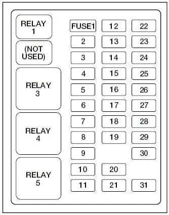
If you’re experiencing electrical issues with your 1999 F250, the key to resolving them lies in understanding the vehicle’s power distribution. Each circuit in your truck is connected to a specific terminal, which is responsible for powering various components. Ensure you have a clear map of where these connections are located to effectively troubleshoot problems.
Knowing the layout of the terminals is crucial for quick diagnosis. Identifying each section of the power panel will help you locate faulty connections, blown components, or misfired circuits. Ensure that you follow the correct order when inspecting each section to avoid missing any potential issue.
Take note of the relay and power supply locations within your truck’s setup. These are often the first points of failure when electrical issues arise, so pinpointing them in advance saves time during repairs. For maximum efficiency, cross-reference the configuration of these sections to ensure proper functioning and avoid costly mistakes during maintenance.
99 F250 Electrical Component Layout
For optimal performance and troubleshooting, refer to the detailed layout of the vehicle’s power distribution system. The component location chart includes precise positioning for relays, circuit breakers, and electrical connections. Each unit is organized by function, ensuring easy access for repairs or upgrades.
The main power system is divided into several sections, each catering to specific vehicle functions like ignition, lighting, and engine management. Understanding the layout ensures quick identification of faulty connections and improves maintenance efficiency. For example, components related to air conditioning, fuel injection, and transmission control are grouped to minimize wiring complexity.
Ensure all connections are securely fastened, and regularly inspect each relay for wear. A detailed reference map should be kept in the vehicle for emergency repairs or diagnostics. Always double-check that components match the specific design of the vehicle to avoid compatibility issues. For long-term reliability, invest in high-quality replacements and consider upgrading to higher-performance alternatives where applicable.
Identifying the Location of the Fuse Box in a 99 F250
The main electrical panel in a 1999 F250 is located beneath the dashboard on the driver’s side, near the steering column. To access it, remove the lower trim panel by unscrewing the fasteners holding it in place. Once the panel is detached, you’ll find the control center with various connectors and relays. A secondary distribution panel is located in the engine compartment, near the driver’s side, close to the fender well. It is accessible by lifting the hood and locating the rectangular cover, which can be removed for maintenance.
Common Circuit Failures and Troubleshooting in the 1999 Power Distribution Panel
Begin by inspecting terminals related to frequently failing systems like the fuel pump, brake lights, and trailer connections. Use a test light or multimeter to verify continuity and power delivery on both sides of each connector pin.
- Fuel Pump Relay Circuit: If the vehicle cranks but doesn’t start, verify the relay socket has constant 12V and a good ground. Replace the relay if it clicks without output.
- Stop Lamp Path: Loss of brake lights often traces back to a blown 20A cartridge. Inspect wiring at the pedal switch and trailer harness for chafing or corrosion.
- Accessory Power Loss: When multiple non-essential systems fail together, check the high-amperage supply links under the hood. Loose connections on the main bus bar are common in older models.
If one section shows consistent overloads, examine downstream components:
- Isolate the affected circuit by unplugging each load (motors, bulbs, modules) one at a time.
- Monitor current draw using a clamp meter to locate any spikes beyond the rated capacity.
- Clean and retighten all grounds on the driver-side kick panel and radiator support.
For persistent issues, remove the affected cartridge and visually inspect for melted plastic or heat discoloration on the panel face–indications of internal arcing. In such cases, panel replacement or pigtail repair may be necessary.
How to Replace Fuses and Ensure Proper Functionality in the 99 Model
Start by switching off the ignition and disconnecting the battery’s negative terminal to avoid any short circuits during the process. Use a non-conductive tool to pull the faulty component from its socket, gripping it by the plastic housing rather than the metal terminals.
Check the internal filament through the transparent shell–if the filament is broken or charred, it must be swapped. Refer to the panel cover or service manual for exact amperage. Never insert a unit with a different rating, as this risks damaging circuits or triggering electrical fires.
Install the new unit by aligning the terminals carefully and pressing it into place until secure. Reconnect the battery and turn on the ignition. Test the affected system–lights, blower, or accessory–to confirm normal operation.
If the new unit fails immediately, investigate the circuit for grounding issues, shorted wires, or failing connected modules before replacing it again. Frequent failures suggest deeper electrical problems requiring professional diagnostics.