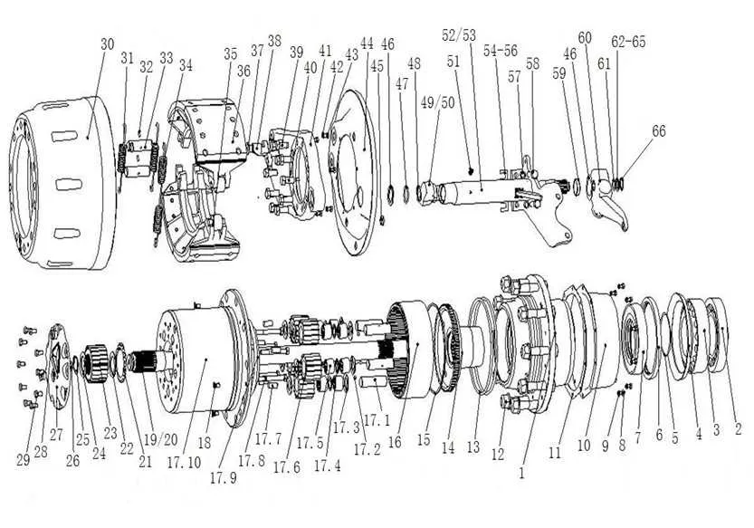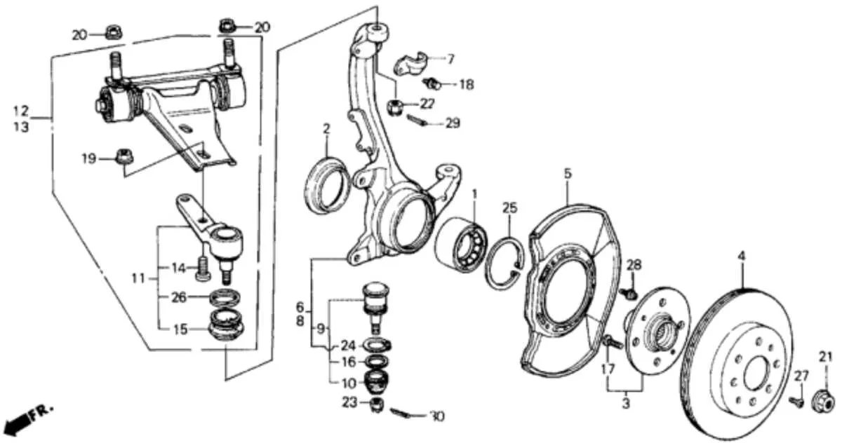
Precise identification of each part in the back axle mechanism ensures effective maintenance and repair. Key elements such as the shell, bearings, cones, and seals require careful attention to guarantee smooth rotation and durability.
Accurate interpretation of the schematic layout is essential for replacing worn pieces or upgrading your drivetrain. Recognizing the position and function of every segment helps prevent premature wear and optimizes performance.
Focus on the interaction between the rotating core and stationary supports to maintain alignment and reduce friction. Proper lubrication points and torque specifications should be strictly followed to extend the lifespan of the entire component set.
Component Layout for the Back Axle Mechanism
To ensure proper installation of the back axle mechanism, start by positioning the central flange securely onto the spindle. Verify that the tapered roller bearings are correctly seated on both sides to maintain smooth rotation under load. Use a calibrated torque wrench to fasten the retaining nut to the manufacturer’s specified value, typically between 30-40 Nm, preventing premature wear or loosening.
Next, insert the dust shield precisely to guard internal parts from contaminants and moisture. Confirm the presence of the locking washer or circlip to avoid axial play. The brake drum or disc should align flawlessly with the flange face to guarantee consistent braking performance and prevent vibration.
Greasing the bearings with high-quality lithium-based lubricant before reassembly extends lifespan and reduces friction. Finally, check the spline engagement between the axle shaft and flange, ensuring it is free from corrosion and properly meshed to transmit torque efficiently without slippage.
Identifying Each Component in a Back Rim Center Mechanism

Start by locating the axle shaft, which serves as the central support for all rotating parts. Surrounding it, you will find the bearing sets–typically tapered roller bearings–that ensure smooth rotation and load distribution. Next, identify the flange plate where the spokes attach; it usually has evenly spaced holes around its circumference.
Check for the locknut and cone system on both ends of the axle; these control bearing preload and prevent lateral movement. The dust seals or rubber gaskets protect internal parts from contaminants and moisture, crucial for longevity. The drive cog or sprocket interface is mounted on the flange side, often secured by a retaining ring or threaded collar.
Pay attention to the freewheel or freehub mechanism, responsible for enabling coasting without pedal movement. This part contains pawls and springs that engage during propulsion. Finally, confirm the presence of spacers or washers that maintain correct component alignment and tension along the axle shaft.
Step-by-Step Guide to Interpreting a Back Axle Component Schematic
Start by identifying the central body where the axle rotates. This core part typically connects to the spokes and houses the bearings. Look for labeled parts such as the bearing cones, locknuts, and axle shaft–each should be distinctly marked with reference numbers or names.
Next, trace the placement of the bearings inside the core. Bearings are often shown as circular elements surrounding the axle, ensuring smooth rotation. Check the direction of the bearing cones and cups, as improper orientation can cause premature wear.
Focus on the locking mechanisms depicted, such as nuts and washers. These secure the axle in place and prevent lateral movement. Their positioning relative to the core and bearings is critical for proper function.
Observe any seals or dust covers illustrated. These components protect internal parts from contaminants and moisture, extending longevity. Their exact location around the core and shaft will be clearly marked.
Lastly, verify the interaction between the flange sections where spokes attach and the central unit. The spacing and alignment shown are vital for tension distribution and structural integrity of the entire rotating system.
Troubleshooting Common Issues Using the Back Rotor Center Schematic

Identify bearing wear by inspecting the carrier unit in the schematic for irregular spacing or misalignment. Follow these steps to resolve frequent malfunctions:
- Noise or Grinding:
- Check for damaged or dry ball bearings within the central mechanism.
- Apply proper lubrication to all moving parts indicated in the exploded view.
- Replace worn seals to prevent contamination.
- Excessive Play:
- Inspect the locknut and cones for looseness using torque values from the schematic.
- Tighten components according to manufacturer specifications to eliminate free movement.
- Examine axle alignment for bending or damage that could cause wobbling.
- Difficulty in Rotation:
- Verify the condition of the ratchet mechanism and pawls as shown in the sectional layout.
- Clean and grease engagement parts to ensure smooth operation.
- Replace springs if tension is insufficient to maintain proper engagement.
- Fluid Leakage:
- Inspect oil seals and dust caps detailed in the parts chart for cracks or wear.
- Replace compromised seals to maintain lubrication integrity.
Utilize the detailed exploded view to cross-reference part numbers and ensure replacements match exact specifications. Adhering to torque settings and lubrication points reduces recurrence of issues and extends component lifespan.