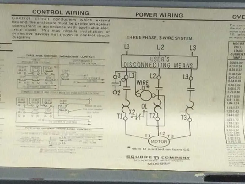
Ensure the proper assembly of your motor control panel by following the specific connection procedures outlined in the provided schematic. Pay close attention to the correct placement of each terminal and component to avoid operational issues. Incorrect wiring can lead to malfunction, damage to equipment, or safety risks.
Identify the key elements of the control circuit: Begin by clearly marking the contacts for the power supply and the actuator. This will guide you in ensuring that both the input and output connections are established without confusion. Connect the components in a way that guarantees the control system responds as expected under load conditions.
Check the voltage ratings: Before proceeding, verify the voltage and current specifications of all parts. Overloaded connections or mismatched components may cause overheating or failure. Always ensure that each element is rated for the operational demands of your setup.
Verify the safety features: Ensure that all protective mechanisms such as fuses, circuit breakers, and grounding are properly installed. These elements safeguard both the machinery and the operators from electrical hazards.
By strictly following these steps, you minimize the risk of malfunction, enhance system longevity, and maintain safety standards in industrial settings.
Connecting a Motor Control Circuit

To ensure proper operation, follow this detailed procedure when setting up a motor control device for industrial use. Proper electrical connections are crucial for the safety and functionality of the system.
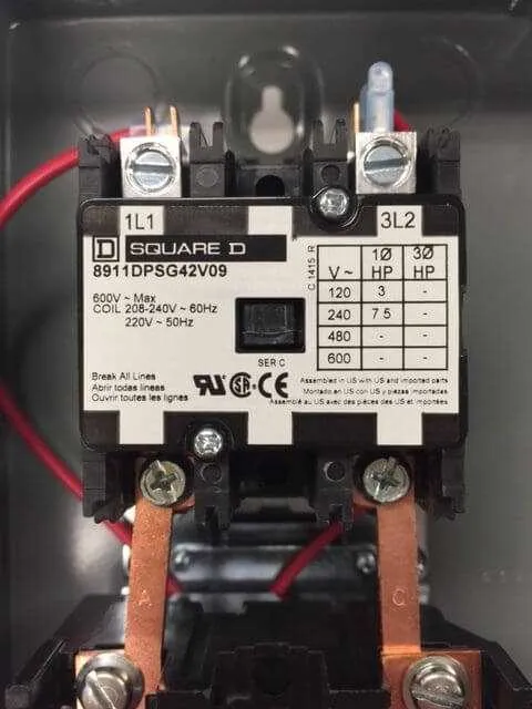
- Begin by identifying the input terminals of the device: the power supply connections should be clearly labeled as L1, L2, and L3 for three-phase systems or L1 and L2 for single-phase configurations.
- Connect the incoming power cables securely to the appropriate terminals, ensuring that the connections are tight to prevent overheating and power loss.
- Next, identify the load terminals, typically labeled as T1, T2, and T3. These are where the motor or other load equipment will be connected.
- Ensure that the control circuit is connected correctly. The coil terminal is where the control voltage should be applied to energize the system. This is commonly achieved by linking the control terminals to a switch or relay.
- Connect the neutral terminal if applicable. For single-phase motors, the neutral is necessary to complete the circuit.
- Make sure to install proper protection for the device. Fuses or circuit breakers should be placed in the input line to prevent damage in case of an overload or short circuit.
For variable frequency drive (VFD) systems, include a connection for the frequency control, typically done through a communication link between the drive and the controller.
- Check the configuration settings for the coil voltage and make sure it matches the supply voltage.
- Inspect the contacts for corrosion or dirt that could disrupt the electrical flow, ensuring smooth operation over time.
Test the setup by applying power, ensuring that the device operates without any unusual sounds, excessive heat, or other irregularities. Monitoring the current draw of the load is also important for verifying that the setup is working within the manufacturer’s specified limits.
Understanding the Main Components of a Motor Control Circuit

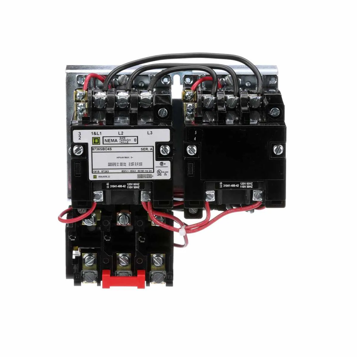
Focus on identifying and connecting the key elements of the motor control system, which include the contactors, overload relays, and auxiliary contacts. These components ensure proper operation, protection, and control of the motor.
The contactor is the most critical element, acting as the switch that controls the power supply to the motor. Ensure that the coil voltage of the contactor matches the control circuit voltage to guarantee reliable operation.
Overload protection is provided by the overload relay, which monitors current levels and disconnects the motor if it draws too much power, thus preventing damage from overheating. Set the overload relay according to the motor’s rated current to avoid nuisance trips.
Auxiliary contacts are used for signaling purposes and interlocking. These contacts help in controlling auxiliary devices, such as indicator lights or alarms, and are critical in ensuring the safety and status monitoring of the motor system.
Lastly, verify the proper installation of control wiring and ensure all connections are secure. Each terminal and wire must be clearly labeled for ease of maintenance and troubleshooting.
Step-by-Step Guide to Connecting a Motor Control Panel
To begin the process, make sure to disconnect all power sources. Safety is paramount, so use insulated tools and wear protective equipment.
1. Prepare the components: Gather the control unit, overload relay, and contactors. Ensure each component is rated for the intended motor load.
2. Wire the main power lines: Connect the incoming three-phase lines to the L1, L2, and L3 terminals of the contactor. Ensure that the power supply is routed to the proper terminals with no loose connections.
3. Connect the motor leads: Run the motor leads from the motor to the output terminals on the contactor. These will typically be marked T1, T2, and T3. Tighten each connection securely to prevent overheating.
4. Set up the overload relay: The relay should be installed between the contactor and the motor. Adjust the settings of the overload protection to the motor’s full load current rating.
5. Control circuit setup: Connect the control circuit wires to the coil of the contactor. The terminals for this will typically be marked A1 and A2. These wires control the activation of the contactor when the start button is pressed.
6. Install the start/stop switch: Wire the start button to the control circuit so that pressing it energizes the coil of the contactor. The stop button should interrupt the circuit to de-energize the coil, cutting power to the motor.
7. Grounding: Proper grounding is essential. Connect the ground wire to the designated grounding terminal of the control panel and ensure that all metal parts are grounded to prevent electrical hazards.
8. Final check: Inspect all connections for tightness and proper insulation. Verify that the control circuit is correctly wired before re-energizing the system. Test the operation by pressing the start button and checking that the motor runs and stops as intended.
Troubleshooting Common Issues in Electrical Control Systems

If the system is not starting, first verify the power supply connections. Check the voltage at the input terminals of the control equipment, ensuring it matches the required levels. A voltage drop could indicate issues with the power source or cables.
If the motor doesn’t run after energizing, inspect the overload relay. A tripped relay can prevent the system from activating. Reset the relay or replace it if necessary. Additionally, ensure the thermal settings are correctly configured for the motor’s specifications.
Check for faulty contacts in the control circuit. If the control switch or push button is malfunctioning, the current may not be properly routed to the system. Use a multimeter to test continuity across the control contacts and replace any defective components.
If the system is overheating, ensure that the cooling fan or ventilation components are working properly. Overheating can also occur if the system is underloaded or subjected to frequent starts and stops. In such cases, re-evaluate the duty cycle and adjust as needed.
If the system experiences intermittent failures, verify the integrity of all connections. Loose or corroded terminals can cause intermittent power loss or inconsistent control. Tighten or clean the connections and check for any signs of wear or damage in the cables.
For issues with delayed activation, inspect the time delay relays. A faulty time delay can cause unnecessary delays in motor activation. Replace or recalibrate the timer to restore normal operation.
When experiencing erratic behavior, check the control transformer for proper grounding. Poor grounding can cause fluctuations or unpredictable control behavior. Ensure all ground connections are secure and free of corrosion.