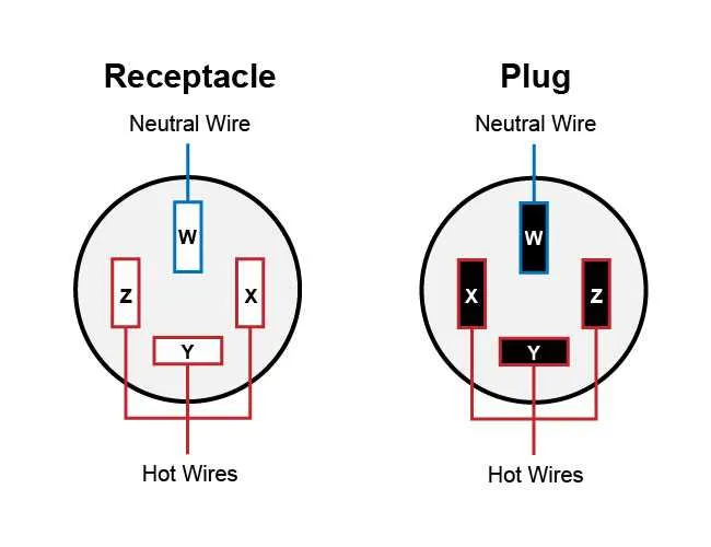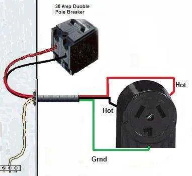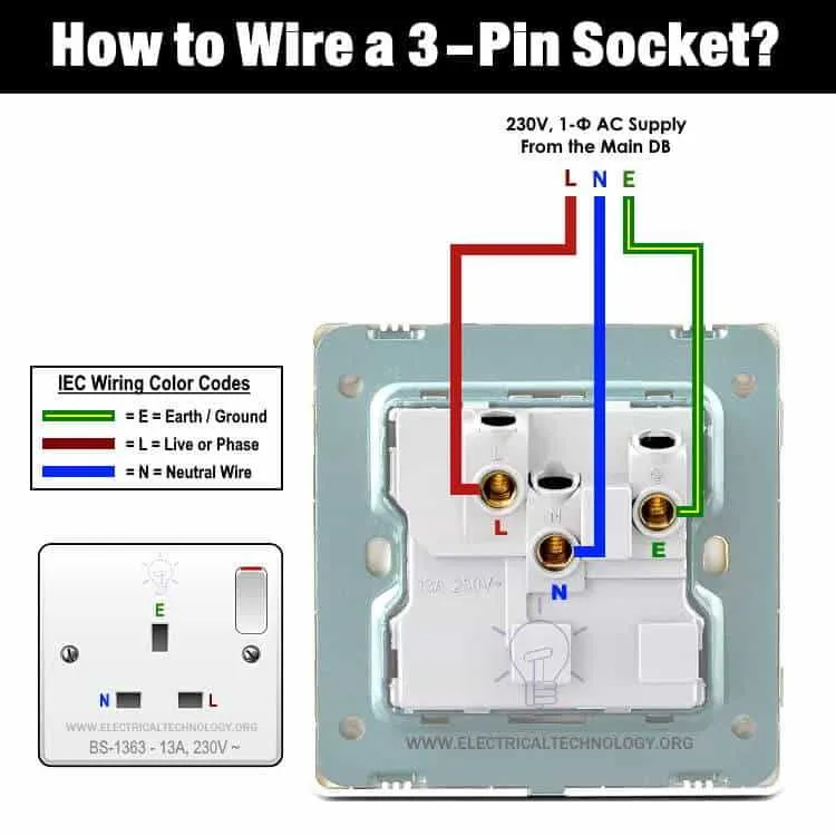
When setting up any system, ensure that the terminals are securely matched to the corresponding wires. Each setup follows a specific sequence for safe and efficient functionality. Follow the manufacturer’s color code or labeling system to avoid misconfigurations that could cause equipment malfunctions or even electrical hazards.
Identify your components: Before starting, gather all necessary parts: outlets, connectors, and wires. Each component will have distinct polarity or power rating, which you must verify before assembling. Incorrect pairings often lead to short circuits or damaged devices, so double-check each link in your circuit.
Step-by-step wiring: Begin with the grounding wire, ensuring it’s tightly fixed to the designated terminal. Next, attach the neutral wire to its corresponding contact, followed by the live wire. It’s crucial to follow this order for proper current flow. Tighten all connections securely to avoid loose contacts, which can lead to overheating.
Test your work: Once the configuration is complete, perform a continuity check using a multimeter. This will help you identify any possible break in the flow. Always test each segment of the setup to ensure that all terminals are correctly wired and no fault occurs before powering up your devices.
Wiring and Socket Configuration

When configuring a power interface, ensure that the conductors are securely attached to the terminal pins. This minimizes risk of poor conductivity and overheating. Follow these steps for proper setup:
- Verify the amperage and voltage specifications for the device to be connected. Make sure the rated current matches the load demand.
- Strip the insulation of the wire carefully, exposing just enough of the conductor to reach the contact points, avoiding exposed metal that could cause short circuits.
- Use the appropriate crimp connectors or screws to secure each wire into the terminal. Tighten connections firmly, but avoid over-tightening which may damage the wire or the terminal.
- Ensure proper color coding for each wire: brown or black for live, blue for neutral, and green/yellow for ground.
Testing is essential to verify that there are no faults or loose connections:
- Use a multimeter to check continuity across all conductors. No reading indicates an issue that requires re-configuration.
- For circuits involving ground, ensure the resistance between the live and ground is minimal to prevent leakage.
Protect all exposed terminals and wire ends with insulation tape or terminal covers to prevent accidental contact. After installation, double-check all components to ensure they are properly aligned and secured before using the system.
Understanding Pin Configuration for Common Electrical Plugs
For safe and effective usage, always check the pin layout before inserting a device. In most configurations, the first pin typically serves as the ground, followed by live and neutral pins, but the arrangement varies based on the standard of your region.
For example, in the UK, the 13A standard has three main terminals: a long ground pin, a shorter live pin, and a neutral pin. The neutral pin is often slightly wider to prevent misalignment during insertion. On the other hand, the EU uses a two-pin format with an optional grounding terminal for safety in more advanced designs.
Pay attention to the shape of the holes or slots to ensure compatibility. The size of the pins in continental formats (such as the CEE 7/7) is standardized, but always double-check if you’re using an adapter or dealing with an older system.
For systems requiring more than three pins, like some high-power units, configurations often add a fourth pin for an additional ground or auxiliary function. In these cases, it’s crucial to verify the voltage ratings for each pin to avoid damaging sensitive equipment.
When working with multi-pin setups, never force the connection into place. If the pin does not align smoothly, it’s likely an indication of incompatibility or wear that could affect performance.
How to Properly Wire a Three-Pronged Power Cord

Start by ensuring the power is off. Remove the outer insulation of the wire, exposing about 3 inches of the inner wires. You should see three colored wires: green (ground), white (neutral), and black (hot).
Begin by attaching the green wire to the terminal marked with a ground symbol. This terminal is usually located at the top of the unit. Secure the wire by twisting it around the screw, ensuring a tight fit to prevent any loose connections.
Next, connect the white wire to the terminal on the opposite side of the ground terminal. This is typically marked with an “N” for neutral. Again, wrap the wire securely around the screw to ensure a firm grip.
Lastly, attach the black wire to the remaining terminal, which is generally marked with a “L” for live or hot. Tighten the screw to ensure the wire is securely held in place.
Once all wires are attached, gently push the wires back into the casing, making sure they do not touch each other or the casing’s metal parts. Close the cover tightly to prevent any accidental exposure of the wiring.
Safety tip: Always double-check the tightness of all connections before using the device. Loose connections can lead to overheating or electrical shorts.
Test the finished assembly with a multimeter to verify continuity and correct wiring before use.
Identifying Safety Standards in Power Socket Designs

Ensure that all power outlets comply with local and international safety regulations, such as IEC 60884-1 or UL 498. These standards outline requirements for construction, materials, and performance under various conditions. For instance, check that the materials used for the housing are fire-resistant and insulated to prevent accidental contact with live terminals. Additionally, verify that the pins or blades are appropriately spaced to prevent mismatched insertion of conductors, which could lead to short circuits.
Proper grounding mechanisms must be incorporated, ensuring that users are protected from potential shock hazards. Safety features like shutters or covers on unused slots also enhance protection, especially in areas accessible to children. Furthermore, the design should include strain relief to prevent damage to the internal wires, which could lead to exposed conductors or overheating.
Always look for compliance marks from recognized safety organizations, such as the CE mark in Europe or the UL listing in the United States, which demonstrate adherence to established safety protocols. These symbols assure consumers that the product has been rigorously tested and meets all necessary safety requirements.