
If you are interested in creating interactive and automated projects, Arduino boards are a popular choice. Arduino allows you to write and upload code to control various electronic components, making it a versatile platform for creating a wide range of projects. One common task in many projects is controlling high-power devices or multiple devices simultaneously, and this is where the Arduino 4 Relay Module comes into play.
The Arduino 4 Relay Module is a handy circuit board that allows you to control up to four independent electrical loads using your Arduino board. Each relay on the module can switch a load of up to 10A at 250V AC or 10A at 30V DC. This makes it suitable for a wide range of applications, including home automation, robotics, and industrial control systems.
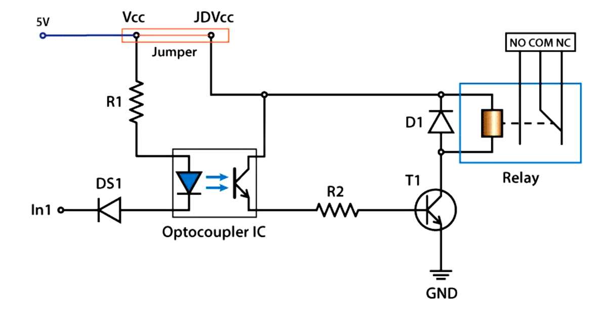
The module is designed to be compatible with various Arduino boards, including the popular Arduino Uno and Arduino Mega. It connects to the Arduino board using digital pins and is powered by the 5V supply from the Arduino board. Additionally, it features four Opto-isolators to provide complete electrical isolation between the Arduino and the relay circuit. This helps protect your Arduino from voltage spikes and electrical noise that could potentially damage it.
In this article, we will explore the schematic diagram of the Arduino 4 Relay Module. Understanding the schematic diagram will allow you to have a deeper understanding of how the module functions and how to incorporate it into your projects. We will cover the key components of the schematic, including the relays, opto-isolators, and driving circuitry. By the end of this article, you will have a solid understanding of the Arduino 4 Relay Module and be ready to incorporate it into your own projects.
Arduino 4 Relay Module Schematic: Understanding the Basics
The Arduino 4 Relay Module is a popular component in the world of microcontrollers and electronics. It provides a convenient way to control up to four relays, which can be used to switch various devices on and off. In this article, we will discuss the basic schematic of the Arduino 4 Relay Module and understand how it works.
At the heart of the Arduino 4 Relay Module is an Arduino microcontroller, which acts as the main control unit. The module also consists of four relays and optocouplers, which provide electrical isolation between the Arduino and the relays. This isolation is crucial to protect the microcontroller from voltage spikes or other electrical disturbances caused by the high current flowing through the relays.
The relay is an electromagnetic switch that can be activated or deactivated by the Arduino. When the microcontroller sends a signal to the relay module, the optocoupler triggers the relay, allowing the current to flow through the switch contacts. This can be used to control various electrical devices like lights, fans, motors, or other appliances.
The Arduino 4 Relay Module schematic typically includes four channels, each consisting of a relay, optocoupler, and related components. The schematic also includes input/output pins for connecting the module to the Arduino, power supply connections, and LED indicators to display the status of each relay. Refer to the specific datasheet or manufacturer’s documentation for the exact pin configurations and specifications.
Understanding the basics of the Arduino 4 Relay Module schematic is essential for effectively using the module in your projects. It enables you to control multiple devices using a single Arduino and provides electrical isolation for safety. Whether you are a beginner or an experienced electronics enthusiast, learning about the Arduino 4 Relay Module schematic is a valuable skill for expanding your capabilities in the world of microcontrollers and automation.
The Functionality of Arduino 4 Relay Modules
The Arduino 4 relay module is a versatile component that allows you to control multiple high-powered devices using a microcontroller such as the Arduino. It consists of four relays, each capable of switching up to 10A, and can be easily interfaced with the Arduino board.
The primary function of the Arduino 4 relay module is to provide a means of controlling high-power devices, such as motors, lights, or valves, using low-power signals from the Arduino. Each relay can be independently controlled with a digital signal from the Arduino, allowing for precise and flexible control of multiple devices.
- The relays on the module are electromechanical switches that are controlled by an electromagnetic coil. When a digital signal from the Arduino is applied to the relay, the coil is energized, causing the switch contacts to close and complete the circuit to the device being controlled.
- The Arduino 4 relay module also includes optocouplers, which provide electrical isolation between the Arduino and the high-power devices. This helps to protect the Arduino from voltage spikes and other electrical disturbances that can occur when switching high-power loads.
- Additionally, the module features status LEDs for each relay, providing visual indication of the relay’s state. This can be helpful for troubleshooting and monitoring the operation of the system.
The Arduino 4 relay module can be easily integrated into a variety of projects that require control of multiple high-power devices. It is commonly used in home automation systems, robotics, industrial automation, and other applications where the ability to switch high-power loads is required.
| Features | Specifications |
|---|---|
| Number of relays | 4 |
| Maximum switching current | 10A per relay |
| Control voltage | 5V |
| Input signal | Digital |
| Interface | Arduino compatible |
In conclusion, the Arduino 4 relay module provides a convenient and reliable solution for controlling high-power devices with a microcontroller such as the Arduino. Its versatility, ease of use, and electrical isolation make it an ideal choice for a wide range of applications.
Components Used in an Arduino 4 Relay Module
The Arduino 4 Relay Module is a versatile electronic device that allows you to control up to four electrical circuits using an Arduino microcontroller. It is commonly used in home automation projects, robotics, and industrial applications. This module provides an easy-to-use interface for controlling appliances, lights, motors, and other electrical devices.
The main components used in an Arduino 4 Relay Module include:
- Relays: The module comes with four relays, which are electromechanical switches that can be controlled electronically. Each relay consists of a coil, a set of contacts (common, normally open, and normally closed), and a diode for protection against back EMF. These relays provide the switching capability for turning the connected circuits on or off.
- Transistors: To control the relays, the module uses transistors, which act as switches to trigger the relays. Transistors, such as the popular NPN transistor like the 2N2222, are used as electronic amplifiers that amplify the signal from the Arduino to drive the relay coils.
- Diodes: Diodes are electronic components that allow current to flow in only one direction. They are used in the module to protect the transistors and Arduino pins from any reverse flow of current generated by the relay coils when they are turned off. Commonly used diodes, such as the 1N4001, are used for this purpose.
- Optocouplers: Optocouplers, also known as optoisolators, are used to provide electrical isolation between the Arduino and the relays. They use light-emitting diodes (LEDs) to transfer electrical signals from the Arduino to the relays without direct electrical contact. This isolation helps protect the Arduino from any voltage spikes or disturbances that may occur when switching the relays.
- PCB (Printed Circuit Board): The Arduino 4 Relay Module is mounted on a PCB, which provides the physical platform for all the components to be soldered onto. The PCB ensures proper connectivity and supports the design of the module.
- Connectors: The module features various connectors, such as screw terminals or female headers, to easily connect and disconnect the external electrical circuits. These connectors allow you to connect the relay contacts to the circuits you want to control.
- Arduino Compatible Pins: The module integrates with an Arduino microcontroller through its dedicated compatible pins. These pins connect with the Arduino’s digital I/O pins, allowing the Arduino to send control signals to the module for switching the relays on or off.
In conclusion, the Arduino 4 Relay Module incorporates relays, transistors, diodes, optocouplers, a PCB, connectors, and Arduino compatible pins to provide an efficient and reliable way to control multiple electrical circuits using an Arduino microcontroller.
Circuit Diagram of an Arduino 4 Relay Module
The Arduino 4 Relay Module is a popular choice for controlling high-power devices with an Arduino board. It allows you to connect up to four separate circuits and control them independently using the digital output pins on the Arduino.
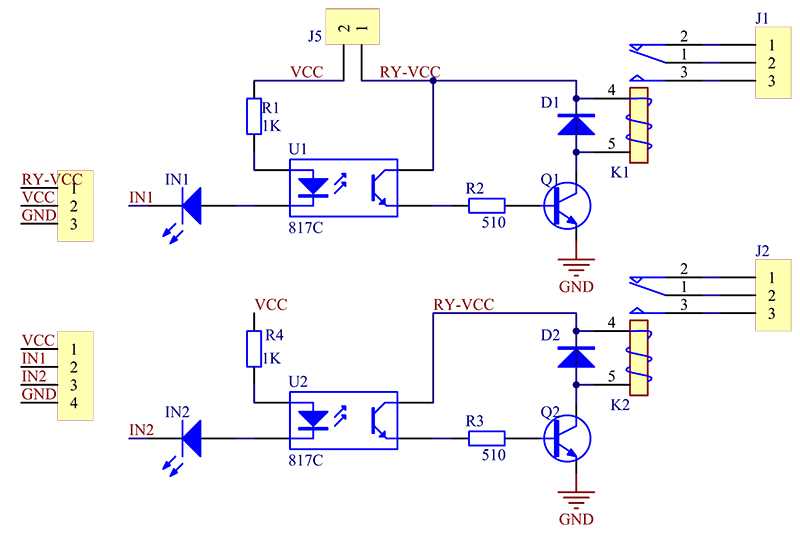
The circuit diagram of the Arduino 4 Relay Module is relatively simple. It consists of four relays, each with its own control circuit, and an interface circuit that connects the relays to the Arduino. The relays are typically represented by rectangular boxes with two coils and two switches inside.
- The control circuit for each relay consists of a transistor, diode, resistor, and an LED. The transistor amplifies the current from the Arduino’s digital pin, allowing it to control the higher current required by the relay. The diode is used to protect the transistor from back EMF when the relay turns off, while the resistor limits the current flowing through the LED.
- The interface circuit connects the digital output pins of the Arduino to the control circuits of the relays. It consists of a series of connections between the Arduino’s digital pins and the input pins of the relays. These connections can be made using jumper wires or a custom PCB.
The Arduino 4 Relay Module can be powered either by the Arduino board itself or by an external power source, depending on the power requirements of the devices you are controlling. The power supply for the relays is connected separately from the Arduino’s power supply, typically using a dedicated power pin on the module.
Overall, the circuit diagram of the Arduino 4 Relay Module is a straightforward and flexible solution for controlling multiple high-power devices with an Arduino. It provides a reliable and safe way to switch on and off various electrical circuits using the digital output pins of the Arduino board.
Understanding the Connections of an Arduino 4 Relay Module
The Arduino 4 Relay Module is a popular electronic component that allows you to control up to four electrical circuits using an Arduino microcontroller. By connecting the Arduino pins to the relay module, you can turn on and off devices such as lights, fans, and motors.
The relay module consists of four individual relays, each with three main connections: COM (common), NO (normally open), and NC (normally closed). When the relay is not energized, the common pin is connected to the normally closed pin. When the relay is activated, the common pin is disconnected from the normally closed pin and connected to the normally open pin. This allows current to flow through or be interrupted in the connected circuit.
The Arduino 4 Relay Module is typically connected to the Arduino board using jumper wires. Each relay is controlled by a specific Arduino digital pin, which can be set to HIGH or LOW to activate or deactivate the relay. The relay module also requires a separate power supply to energize the relays and control the connected devices.
To connect the Arduino 4 Relay Module, you will need to make the following connections:
- Connect the VCC pin of the relay module to the 5V output pin of the Arduino board.
- Connect the GND pin of the relay module to the GND pin of the Arduino board.
- Connect each IN pin of the relay module to a specific digital pin of the Arduino board.
- Connect the JD-VCC pin of the relay module to the external power supply’s positive terminal.
- Connect the GND pin of the external power supply to the external power supply’s negative terminal.
- Connect the VCC and GND terminals of the external power supply to the devices you want to control.
Once the connections are made and the Arduino code is uploaded, you can use the Arduino IDE to control the relays. By setting a specific digital pin to HIGH, the corresponding relay will be activated and the connected device will turn on. Setting the digital pin to LOW will deactivate the relay and turn off the device.
The Arduino 4 Relay Module provides a convenient and versatile solution for controlling multiple electrical circuits using an Arduino. With a basic understanding of the connections and some programming knowledge, you can easily integrate this module into your projects and automate various devices.
Working of an Arduino 4 Relay Module
The Arduino 4 Relay Module is a device that allows you to control up to four different electrical circuits using your Arduino board. It provides an easy way to switch and control high voltage loads such as lights, motors, and other appliances with the help of digital signals from the Arduino.
The module consists of four relays, which are electromagnetic switches that can be controlled by the Arduino. Each relay has a normally open (NO) and a normally closed (NC) contact. When the relay is energized, the NO contact connects to the common (COM) terminal, completing the circuit, while the NC contact disconnects. When the relay is not energized, the NO contact disconnects while the NC contact connects.
The Arduino 4 Relay Module can be connected to the Arduino board through its digital pins. The Arduino sends digital signals (high or low) to these pins to control the state of the relays. By programming the Arduino, you can determine when and how the relays should be switched on or off, based on various conditions or inputs.
When you want to control a high voltage load using the Arduino 4 Relay Module, you need to connect the load to the common (COM) terminal of the corresponding relay, and connect the NO or NC contact to the power source or ground accordingly. By activating and deactivating the relays using the Arduino, you can switch the load on or off, providing control over various electrical circuits.
The Arduino 4 Relay Module is a versatile and cost-effective solution for home automation projects, DIY electronics, and industrial applications. With its ability to interface with the Arduino board, it enables precise control and automation of electrical devices, making it a valuable component in many projects.
Troubleshooting Tips for Arduino 4 Relay Modules
If you’re experiencing issues with your Arduino 4 relay module, don’t worry! There are some common problems that can be easily fixed with a few troubleshooting steps. Here are some tips to help you get your relay module working properly:
1. Check the Wiring
Make sure all the wires are connected correctly and securely. Check for any loose connections or broken wires. Double-check that the relay module is properly connected to the Arduino board.
2. Verify the Power Supply
Ensure that the power supply is delivering the correct voltage to the relay module. Check if the input and output voltages match the specifications of the module. If the voltage is too high or too low, it may cause issues with the relays.
3. Test Each Relay Individually
If one or more relays are not functioning, try testing them individually. Disconnect all connections except for the relay you want to test. This will help you identify if the issue is with a specific relay or the entire module.
4. Check for Interference
Interference from nearby electronic devices can sometimes affect the operation of the relay module. Try moving the module to a different location or shield it from potential sources of interference.
5. Update Arduino Library and Sketch
Ensure that you have the latest version of the Arduino library and sketch for controlling the relay module. Check if there are any updates available and install them. Sometimes, outdated software can cause compatibility issues.
6. Test with Different Arduino Board
If you have access to another Arduino board, try connecting the relay module to that board and see if the issue persists. This will help you determine if the problem is with the relay module or the Arduino board itself.
7. Seek Help from the Community
If you’ve tried all the troubleshooting steps and are still unable to resolve the issue, it can be helpful to seek assistance from online Arduino communities or forums. Many experienced Arduino enthusiasts are willing to help troubleshoot and provide solutions.
By following these troubleshooting tips, you should be able to identify and resolve common issues with Arduino 4 relay modules. Remember to always double-check your connections and consult the module’s documentation for any specific troubleshooting steps.