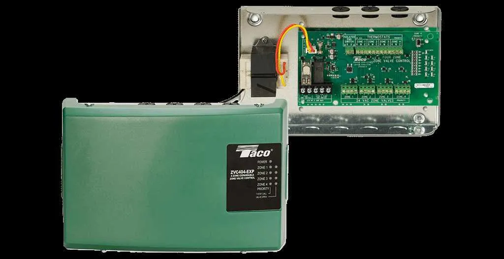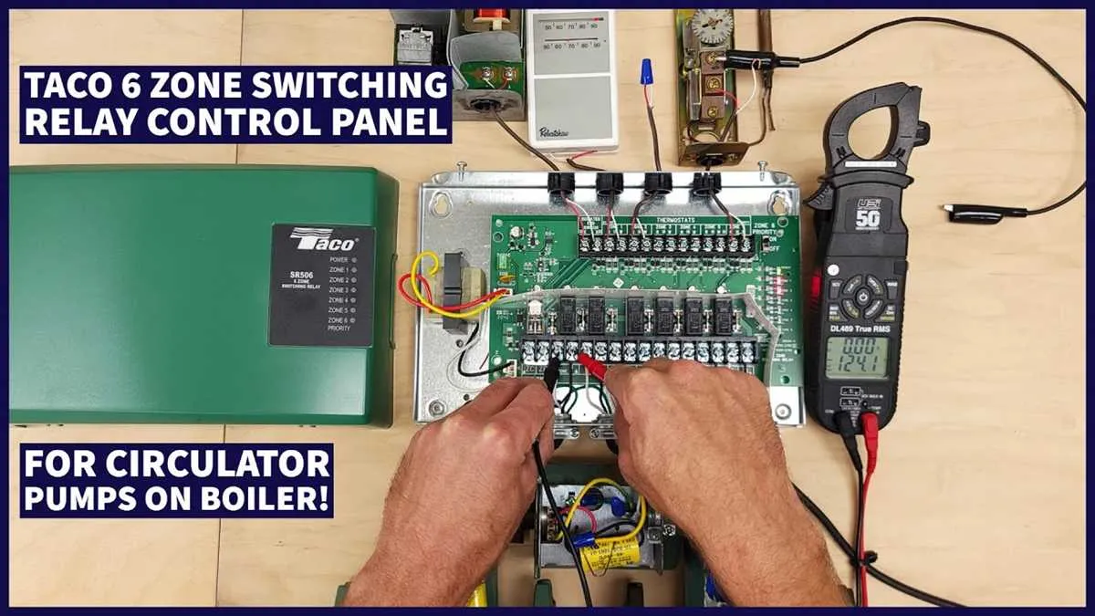
For optimal operation of your heating system, ensure that each control device is wired correctly. Start by checking the wire connections to the primary switching component that regulates the flow of heated water. Miswiring can lead to system failures or reduced efficiency.
Each zone controller is equipped with specific terminals for incoming power and signal wires. Use high-quality, durable wiring to avoid overheating and potential system damage. Be sure to connect the system’s power supply to the designated terminal, and make sure all terminals are tightly secured.
Next, inspect the control switch that triggers the flow of water to each section of the system. The actuating mechanism should be properly aligned with the corresponding contacts, ensuring that each segment activates only when required. Confirm that the device is properly grounded to prevent electrical issues.
For troubleshooting, always double-check the wire placements by referencing the manufacturer’s manual. Incorrect connections, especially with control circuits, can prevent the heating system from working efficiently, leading to unnecessary energy consumption.
Electrical Connections for Multi-Heating Control Units
For accurate installation, always use a 24V transformer to power the control system. Connect the power supply to the common terminal (C) and the normally open contacts (NO) on your relay. This configuration allows a reliable signal to activate the system when needed. Ensure the thermostat is linked to the control board through its corresponding terminals, typically marked as T1 and T2.
Each heating loop should have a dedicated control relay that gets energized upon reaching the required temperature, switching the circuit to activate the connected pump. Confirm the correct placement of the heat sensors, ensuring they are properly wired to the control panel for accurate feedback.
Make sure the isolation switch is installed to prevent accidental activation during maintenance. For ease of future troubleshooting, label all connections clearly and use high-quality, insulated wiring to prevent short circuits. Always test the unit’s performance after setup, checking that each circuit responds appropriately to temperature changes.
When linking multiple circuits, consider using an intermediary relay or a multi-port controller to handle the different zones independently. This method ensures each section operates on its own schedule without interference. Proper grounding is essential to avoid electrical surges that could damage your equipment.
Understanding Taco Zone Valve Wiring Connections

When connecting the components of a multi-zone heating system, ensure that the power supply is isolated before starting the installation. First, identify the terminals on the actuator motor: two for the common connection and two for control inputs. The common terminal is usually connected to the neutral wire, while the control terminals are used for connection to the thermostat or controller. Ensure the wires are tightly secured, preventing any loose connections which could result in operational failure.
For proper functionality, link the system’s control wire (usually a red or white wire) to the actuator’s input terminal responsible for activation. If using a relay, the connection between the relay and the actuator must be established properly to allow activation when heating demand is present. Make sure that the power to the system is off before making any modifications to prevent electrical hazards.
The system’s control must send the correct signal to initiate the actuator’s movement, opening or closing the flow based on the thermostat settings. Always check that the power ratings match between the actuator and the control system to avoid malfunction or damage to the components.
Labeling each wire connection clearly can help with troubleshooting in the future. Always test the system after installation to confirm that each zone activates correctly when the thermostat calls for heat. Use a multimeter to check for proper voltage at the actuator terminals.
Step-by-Step Guide to Troubleshooting Valve Control System Wiring Issues
1. Check the Power Supply
Ensure the system is receiving power. Use a multimeter to confirm that the transformer is working and providing the correct voltage to the system. If there’s no power, verify the fuse or circuit breaker and replace if necessary.
2. Inspect the Control Board
Examine the control panel for any visible signs of damage or burned components. A malfunctioning board can cause issues with switching mechanisms. If damaged, replacing the board is the most effective solution.
3. Test the Switches and Actuators
Check the actuators for proper function. They should respond when triggered. If they don’t, remove the actuator and test it independently by applying the recommended voltage. A faulty actuator needs replacement.
4. Verify Connection Integrity
Inspect all connections for signs of wear, corrosion, or loose terminals. Ensure that each wire is securely connected to its designated terminal. Tighten any loose connections and replace wires showing wear or damage.
5. Troubleshoot the Relay Circuit
If the relay doesn’t activate, the control board may not be sending the proper signals. Check the relay coil and contacts for any faults. Replace the relay if it’s not functioning properly.
6. Confirm Thermostat Operation
Ensure the thermostat is correctly set and communicating with the control system. If the thermostat is faulty, it may fail to send the correct activation signal to the control system. A malfunctioning thermostat should be calibrated or replaced.
7. Check for Electrical Short Circuits
Examine the system for any short circuits or signs of electrical overheating. A short can disrupt the entire operation. Use a continuity tester to identify any unwanted connections and replace the affected components.
8. Inspect for Proper Grounding
Ensure the system is properly grounded. Improper grounding can cause erratic behavior, including malfunctioning of sensors and actuators. Re-establish the ground connection if needed.