To ensure a stable network connection, follow the color-coded sequence used in the Ethernet connectors. Adhering to the correct order of wires inside the plug is crucial for proper functionality. The most common configurations are T568A and T568B, each with slight differences in the arrangement of colored cables.
T568A is often used in residential installations and is compatible with most home networking devices. The order begins with white-green, followed by green, white-orange, blue, white-blue, orange, white-brown, and brown.
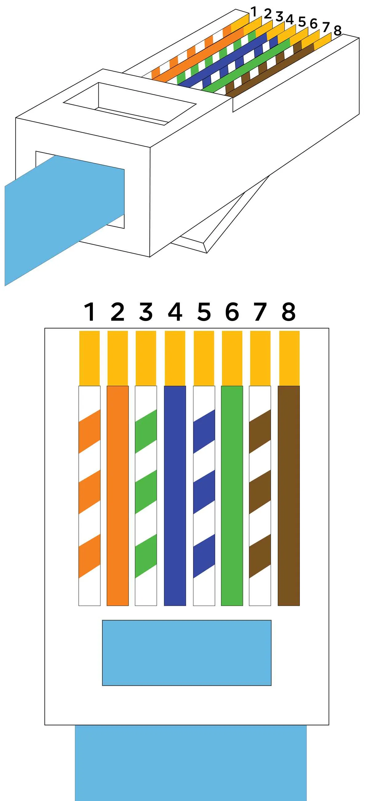
T568B, on the other hand, is more commonly seen in commercial applications and offers a similar structure but with different color assignments, starting with white-orange, followed by orange, white-green, blue, white-blue, green, white-brown, and brown.
For optimal performance, always use the same standard on both ends of the cable. Mixing standards between devices can result in connectivity issues and reduced network speed. If you are uncertain which configuration to use, verify the setup on your existing equipment or consult with a professional to avoid any potential problems.
Proper Pin Configuration

To ensure optimal network performance, adhere to the following pin assignments. For straight-through connections, use the 568B standard which is widely adopted in Ethernet setups. The correct order of pins, from left to right (clip facing you), is as follows:
1: White with orange stripes
2: Solid orange
3: White with green stripes
4: Solid blue
5: White with blue stripes
6: Solid green
7: White with brown stripes
8: Solid brown
For crossover connections, swap the pairs on the opposite ends. This configuration allows two devices to communicate directly without a hub or switch.
Ensure all conductors are properly seated in the connector and that the jacket is secured under the strain relief to prevent connection issues.
Understanding the Color Code for RJ45 Wiring
When assembling a network connection, the correct placement of wires is crucial for proper functionality. The color sequence you choose for each conductor impacts the performance and compatibility of the connection. Below is a clear breakdown of standard color codes that ensure optimal signal transmission.
- Pin 1: White with blue stripes (Blue – T568B) or White with green stripes (Green – T568A)
- Pin 2: Blue (Solid – T568B) or Green (Solid – T568A)
- Pin 3: White with orange stripes (Orange – T568B) or White with brown stripes (Brown – T568A)
- Pin 4: Orange (Solid – T568B) or Brown (Solid – T568A)
- Pin 5: White with green stripes (Green – T568B) or White with blue stripes (Blue – T568A)
- Pin 6: Green (Solid – T568B) or Blue (Solid – T568A)
- Pin 7: White with brown stripes (Brown – T568B) or White with orange stripes (Orange – T568A)
- Pin 8: Brown (Solid – T568B) or Orange (Solid – T568A)
It’s essential to note that the color coding follows two primary standards: T568A and T568B. Both are functionally equivalent, but the wire pairing differs. Most common installations use T568B, but it’s important to check existing systems for consistency before proceeding.
Incorrect wire alignment can lead to network failure, poor signal quality, or even total connection loss. Always ensure that the wiring follows a precise order as per the chosen standard. This will guarantee a reliable and high-speed connection, particularly for high-performance setups such as Gigabit Ethernet.
How to Choose the Right Wiring Standard for Your Network
Select the appropriate configuration based on the speed and distance requirements of your system. For high-speed connections up to 1 Gbps over short distances, the T568B standard is sufficient. If you require speeds of up to 10 Gbps, especially for longer cables (above 100 meters), T568A or B standards with proper shielding are recommended to minimize interference and signal degradation.
For business environments with heavy data traffic, opting for the T568B is more common due to its widespread use in commercial installations. It offers better compatibility with most networking hardware. For home setups where cost is a factor and performance is not as demanding, the T568A configuration may suffice.
Consider using twisted-pair cables that support Cat5e or Cat6 ratings to meet modern standards, ensuring that your network can handle higher speeds and increased demand without issues. Always check the maximum length allowed to avoid signal loss, which typically decreases over distances exceeding 90 meters.
If electromagnetic interference (EMI) is a concern, particularly in industrial or densely populated environments, opt for shielded twisted pair (STP) cables to ensure signal integrity over longer distances. The right choice will enhance your network’s reliability and future-proof your infrastructure for upcoming technologies.
Step-by-Step Guide to Creating a Custom RJ45 Cable
Start by cutting the desired length of Ethernet cable with a sharp tool, leaving extra length to ensure flexibility for adjustments. Strip about 1.5 inches of insulation from both ends of the cable using a wire stripper, exposing the individual copper wires.
Arrange the color-coded wires in the correct order based on the preferred wiring standard. Use the T568A or T568B configuration, depending on the required network setup. Align the wires neatly, ensuring they are in the correct sequence and laid out flat for easy insertion into the connector.
Trim the exposed wires to an even length, approximately half an inch, ensuring they fit snugly inside the connector. Insert the wires into the RJ45 plug one at a time, ensuring that each wire reaches the end of the connector and is in the correct slot.
Use a crimping tool to secure the connector, pressing down firmly until the metal pins inside the plug make contact with the copper wires. This step is critical for ensuring proper electrical connectivity. Check that the cable is securely inserted into the connector before proceeding.
Repeat the process on the other end of the cable, making sure both ends have the same configuration and wire order. Test the completed cable using a network tester to confirm there are no misalignments or connectivity issues.