If you’re working with heavy machinery or diesel-powered vehicles, understanding the inner workings of the propulsion system is essential. The assembly consists of numerous interconnected elements that require precise alignment and optimal functioning. Whether you’re troubleshooting an issue or performing routine maintenance, having a clear visual reference can make all the difference in ensuring efficiency and performance.
For a detailed understanding of these systems, focus on the key components like pistons, turbochargers, fuel injectors, and timing mechanisms. These parts play critical roles in energy conversion and emission control. It’s important to familiarize yourself with their placement, function, and potential failure points to troubleshoot effectively and prevent downtime.
Use a structured guide to pinpoint the exact arrangement of each part within the setup. This can help identify specific areas that might need attention during regular service intervals. For those unfamiliar with the mechanical layout, professional tools and schematics can simplify the process, making it easier to perform diagnostics and repairs.
Always ensure that you’re working with the correct specifications for the model you’re servicing. Each setup might have slight variations in configuration depending on the vehicle’s make and purpose. Therefore, cross-referencing the parts’ locations with a verified chart is highly recommended for accurate identification and replacement.
Understanding the Key Components of a Diesel Power Unit

To ensure optimal performance, regularly inspect the fuel injectors and turbochargers, as these are crucial for the efficient combustion process. Their maintenance directly impacts the overall efficiency and power delivery.
Timing components, such as camshafts and timing gears, should be checked periodically for wear, as timing discrepancies can lead to poor performance and engine misfires. Replacing these before failure can save significant repair costs.
The cooling system is another critical area. Ensure that the radiator and water pump are functioning properly to prevent overheating. Regular inspection of hoses and seals for leaks will help maintain an effective cooling cycle.
Inspect the oil pump and crankshaft regularly. Low oil pressure can lead to severe damage, while an imbalanced crankshaft can cause vibrations and long-term wear. Replacing filters and monitoring oil levels is essential for the longevity of the unit.
The alternator and battery must be regularly tested to avoid electrical system failures. Keeping the system charged and checking connections will prevent power interruptions that can affect other subsystems.
Exhaust systems are also critical. Monitor for any blockages or damage that could affect airflow and performance. A clogged exhaust filter can result in higher emissions and reduced engine power.
Finally, keep an eye on lubrication and fuel lines to avoid contamination or clogging. Regularly replacing filters and ensuring proper fuel delivery will maintain smooth operation and prevent costly breakdowns.
Identifying Key Components for Maintenance
To ensure optimal performance, focus on the following critical components during regular checks and maintenance:
- Fuel Delivery System: Inspect the fuel pump, injectors, and fuel lines for blockages or leaks. Regularly clean or replace filters to avoid contamination.
- Air Intake Assembly: Check the air filter and intake manifold for debris. A clogged filter can reduce efficiency and increase wear on internal components.
- Cooling System: Maintain proper coolant levels and check for leaks in hoses and radiators. Clean the radiator fins to prevent overheating.
- Lubrication System: Regularly inspect oil levels and quality. Change the oil as per manufacturer guidelines and replace the oil filter to avoid sludge buildup.
- Exhaust Components: Examine the exhaust manifold and turbocharger for signs of wear or damage. Clean soot deposits to maintain air flow and prevent blockages.
- Timing Mechanism: Ensure the timing belts and gears are intact and not showing signs of excessive wear. Replacing worn-out belts prevents internal component damage.
- Electrical System: Test the alternator, battery, and starter motor. Corrosion or loose connections can result in inconsistent performance.
Regular inspections of these components are essential to avoid costly repairs and downtime. Prioritize components based on the system’s performance and manufacturer specifications.
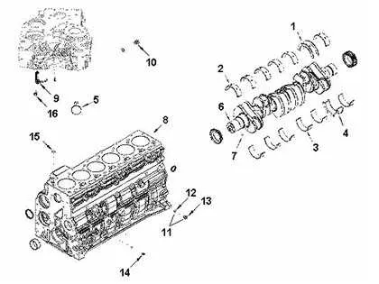
How to Read and Interpret a Cummins Engine Parts Diagram

To understand a schematic of the power unit, focus on identifying the different sections marked by numbers or codes. Each section represents a specific component, usually with a label or reference key. Begin by locating the key or legend, which will explain the meaning of each symbol and color used in the illustration.
Pay attention to the component groupings. These are typically organized into categories such as fuel systems, cooling elements, and electrical connections. Each grouping shows the relationship between different elements, making it easier to locate specific parts or troubleshoot issues.
Follow the flow lines and arrows. They often indicate the movement of fluids, air, or electrical signals. Understanding these connections helps in diagnosing malfunctions or understanding how the system operates as a whole.
When looking for replacement parts or troubleshooting, cross-reference the part numbers in the schematic with the list provided in the manufacturer’s catalog or service manual. These will allow you to identify the exact specifications of each component.
Use color coding or shading to your advantage. Different colors may represent various operational states, such as active, idle, or fault conditions, which can be helpful for diagnostics.
Finally, if a part’s location is unclear, zoom into the schematic if possible, or refer to multiple views to get a better understanding of the part’s placement in relation to the system as a whole.
Common Issues in Diesel Power Systems and How to Spot Them in a Visual Representation
Cracked Pistons are a frequent issue. In a visual representation, look for visible cracks or chips on the piston surface. This often occurs due to overheating or poor lubrication, and can lead to a loss of compression and decreased performance.
Worn-out Bearings can result in unusual vibrations and excessive noise. Check for discoloration or scoring in the bearing areas. In a visual schematic, worn bearings often appear as darkened spots or areas with uneven wear patterns.
Leaky Seals often cause fluid loss and contamination. Examine the seals for any irregularities, such as bulging or wear, especially around the piston rings and valve seats. Leaky seals are commonly visible as dark spots or fluid traces in the diagram.
Faulty Fuel Injectors can cause misfires or poor fuel efficiency. In a system overview, you can identify these by looking for irregular spray patterns or deposits on the nozzle. Pay attention to areas where the fuel injectors connect to the system for corrosion or damage.
Clogged Filters can restrict airflow and fuel delivery, leading to poor performance. On a system map, dirty or clogged filters appear darker or discolored. Ensure to trace the flow direction and check for any buildup in the filter zones.
Cracked Cylinder Head is another critical failure. It often occurs due to excessive heat or stress. Check for visible cracks or warping in the head. These issues might show as irregular surfaces or gaps when examining the component.
Damaged Timing Belts can cause synchronization issues, leading to engine misfires or failure to start. In the visual schematic, inspect the belt for fraying or missing teeth, especially where it runs along pulleys and tensioners.
Excessive Carbon Build-up occurs over time in high-pressure areas. This can be spotted as black deposits or residue in components like valves or turbochargers. Look for areas with thick, dark layers that could impede normal function.