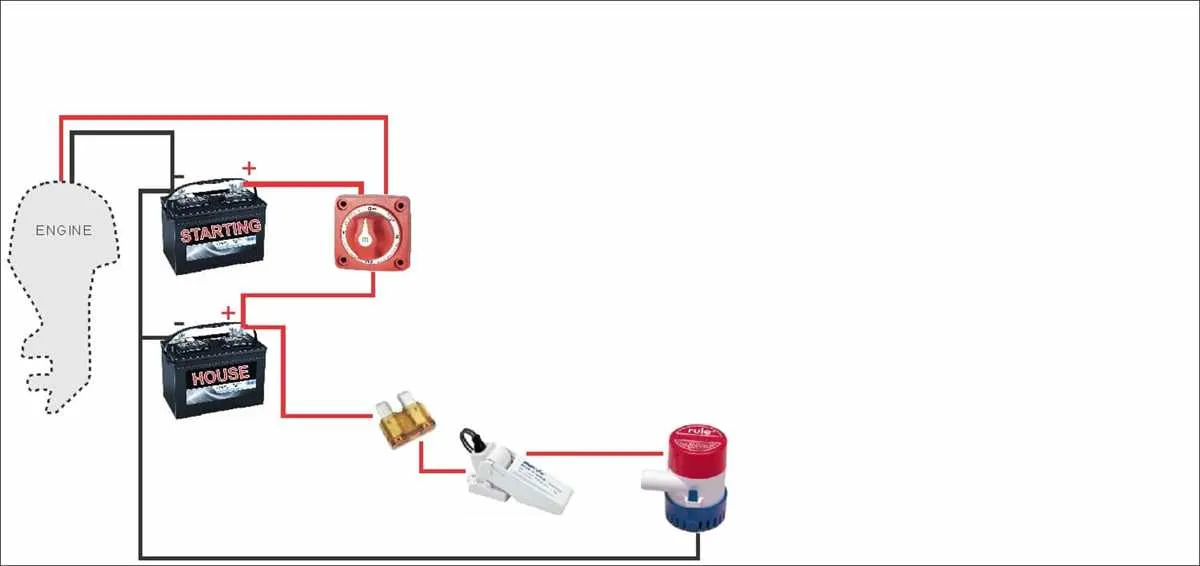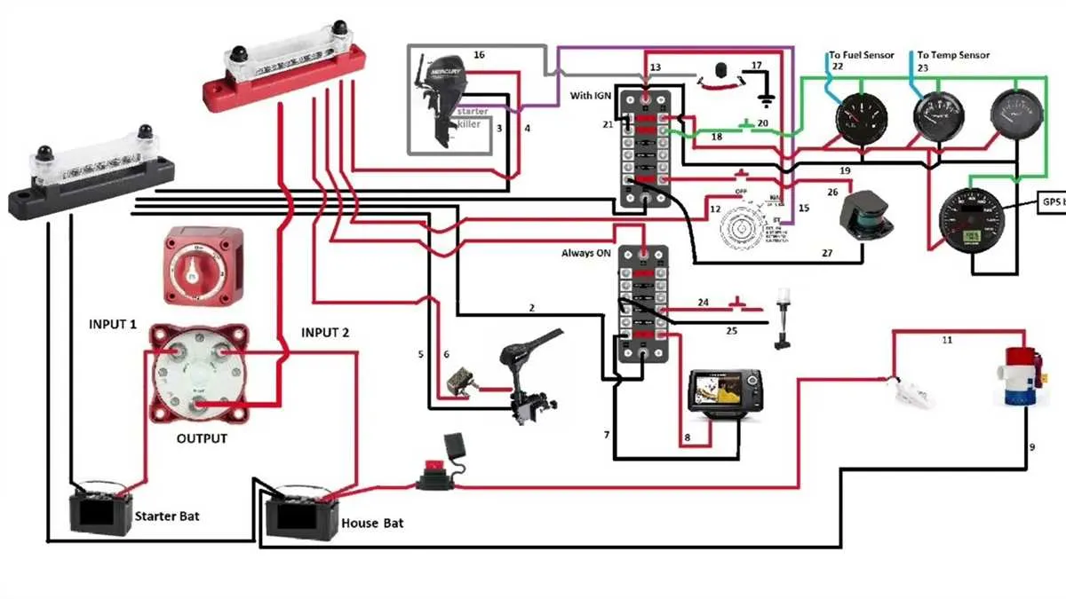
Connect the primary engine-driven unit directly to the starter cell and route all house electronics through an isolated auxiliary cell. This separation ensures that essential propulsion functions remain unaffected by accessory consumption.
Use an automatic relay to link both energy units during charging. This device engages only when voltage exceeds a specific threshold, typically 13.2V, allowing simultaneous recharge without manual intervention. Once the engine is off, the link disengages, preserving the starter unit.
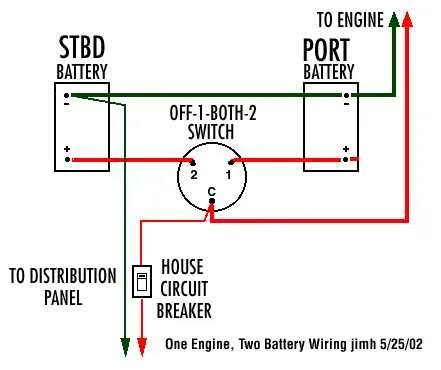
Include a manual switch as a fallback for emergency starts. A common option is a three-position switch marked 1–ALL–2. In normal use, keep it on 1 for ignition or 2 for auxiliary draw. The ALL setting temporarily combines sources if one is depleted.
Ensure proper gauge thickness for all connections, particularly between the cells and the selector. For a setup under 10 feet, 4 AWG is generally adequate, but consult amperage tables to confirm compatibility with your system’s load.
Install fuses within seven inches of each power source. Choose ANL or MRBF types with a rating 25% above expected peak draw. Overcurrent protection is not optional–it prevents thermal events in case of insulation failure or shorts.
Efficient Setup for a Two-Power-Source Marine Circuit

Use an isolated switch system with an ACR (Automatic Charging Relay) to ensure both energy units charge from a single alternator without cross-discharge. Prioritize independent cabling for each power cell to minimize voltage drop and avoid interference.
- Install a selector switch (1-2-Both-Off) between energy cells and the main distribution panel.
- Place the ACR between the positive terminals to automate charging while maintaining separation when voltages differ.
- Ground each unit independently to a common bus bar linked to the engine block.
- Fuse all positive lines within 7 inches of each unit’s terminal using ANL or MRBF types.
- For trolling systems, isolate the auxiliary cell completely from the engine circuitry using a manual disconnect.
- Use marine-grade, tinned copper cable (minimum AWG 4 for short runs, AWG 2 or 1/0 for longer routes).
- Label all connections clearly to prevent confusion during maintenance or emergency switchovers.
How to Wire a Dual Battery Setup with an Isolator Switch
Start by installing a selector switch rated for marine use, ideally with OFF, 1, 2, and BOTH positions. Mount it close to the energy storage units and within reach of the operator’s station.
Use heavy-gauge marine-grade cable (minimum 2 AWG) to connect the positive terminal of the first power cell to terminal 1 on the switch. Repeat the process for the second power source, linking its positive to terminal 2.
Connect the common output of the switch to the main distribution panel or starter solenoid using the same gauge cable. Ensure tight connections with tinned copper lugs and seal all terminals using heat shrink tubing.
Join the negative posts of both storage modules with a heavy-duty ground strap and connect this unified ground to the common bus or engine block. Avoid grounding through the hull or relying on a single strap for both banks.
To add an isolator, wire it inline between the alternator’s output and the positive leads going to each accumulator. Choose a voltage-sensitive relay (VSR) rated for the combined current draw to automatically manage charging without manual input.
Secure all lines with cable ties and route them away from heat sources, moving parts, and moisture-prone zones. Label each line clearly for maintenance ease and safety compliance.
Choosing the Right Cable Size and Fuse Ratings for Dual Battery Systems

For runs up to 10 feet carrying 100 amps, use 2 AWG copper conductors. For the same load over 20 feet, upgrade to 1/0 AWG to avoid excessive voltage drop. Always calculate total length as the round-trip distance.
Fuse each positive lead as close as possible to the power source. For systems handling up to 100 amps, a 125A ANL fuse provides effective overcurrent protection while allowing short surges. Ensure fuse ratings match or slightly exceed expected continuous load but remain well below the conductor’s ampacity.
Refer to ABYC E-11 standards: for example, 4 AWG should never be fused above 150A. Never oversize fuses to compensate for voltage drop – increase conductor thickness instead.
Use marine-grade tinned copper wire with temperature ratings of 105°C. Avoid automotive cables, which may have insufficient insulation or corrosion resistance in high-humidity environments.
Troubleshooting Voltage Drop and Charging Issues in a Two-Source Power Setup

Measure voltage at the terminals under load to identify excessive drop. A loss greater than 0.3 volts indicates poor connections or undersized cables. Use cables rated for at least 10% more current than the maximum expected draw, typically AWG 4 or thicker for runs over 10 feet.
Inspect all connection points for corrosion, loose terminals, or oxidation. Clean contacts with a wire brush and apply dielectric grease to prevent future resistance buildup. Tighten bolts to manufacturer torque specs, usually around 8-10 ft-lbs for M6 hardware.
Check isolator or selector switches for wear or internal faults. Faulty switches can cause uneven charge distribution or total failure to pass current. Replace mechanical units with solenoid-based or automatic isolators for more reliable operation.
Verify the alternator output at the input side of the charging controller. It should read 13.8 to 14.4 volts during engine operation. Readings below 13.5 volts suggest regulator problems or wiring losses upstream.
Ensure proper grounding by testing resistance between the negative terminal and the vessel’s common ground. Values should be below 0.05 ohms. High resistance causes erratic charging and voltage drops.
Implement fuse or circuit breaker checks to rule out partial openings or corrosion inside terminals, which can mimic open circuits. Use thermal imaging if available to spot hot spots indicating excessive resistance.
For charging imbalance, confirm both storage units receive current flow by measuring voltage individually during charge. If one unit lags by more than 0.5 volts, investigate isolator integrity or cable condition.