For efficient maintenance and troubleshooting of the cutting machine’s propulsion system, understanding the precise arrangement of the transmission loop is critical. Start by locating the main traction belt, ensuring it aligns correctly with the engine pulley and the twin steering drives. Misalignment or wear can cause slipping or uneven movement.
Inspect tension and routing carefully to prevent premature wear or damage. Follow the path from the motor shaft through the idler pulleys and ensure that each guide roller is positioned as per manufacturer specifications. Correct positioning guarantees smooth directional control and power delivery to the wheels.
Regular replacement of worn loops based on visual checks or operational symptoms helps maintain optimal performance. Pay attention to cracks, fraying, or glazing on the rubber surfaces, which indicate it’s time for a swap. Proper installation requires attention to the engagement points on the transmission arms and the drive hubs for seamless maneuverability.
Drive System Layout for Snapper Mowers

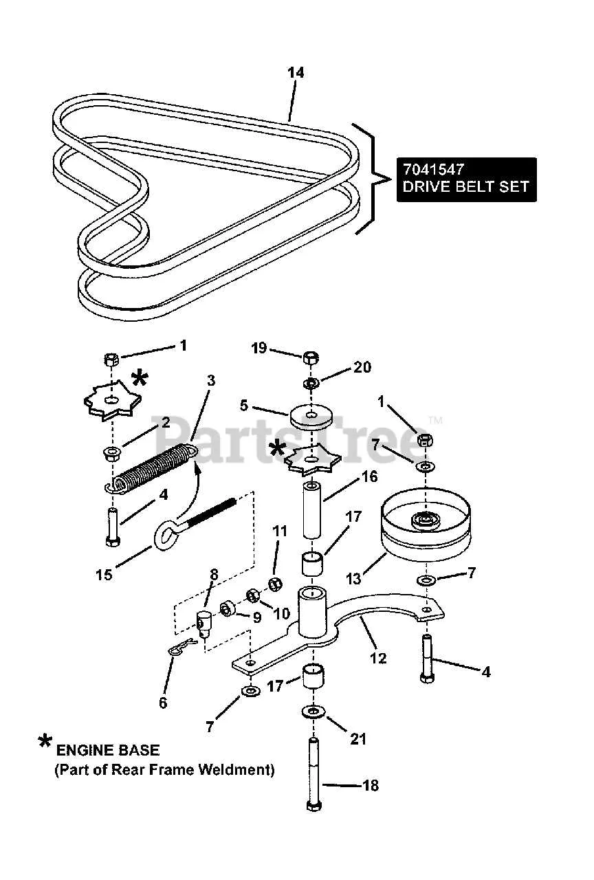
Consult the specific schematic illustrating the routing and positioning of the primary drive bands on Snapper mowing units with pivot steering. Accurate belt placement ensures optimal power transfer from the engine to the traction wheels, preventing slippage and premature wear.
The upper section of the illustration highlights the routing around the engine pulley and tensioner, while the lower part details the engagement with the dual traction pulleys beneath the chassis. Proper alignment with idler pulleys is critical to maintain consistent tension during operation.
Replacement procedures require attention to the routing path: the drive band must loop under the deck and around the forward traction components without twisting. Adjust tensioners to factory specifications to avoid excessive strain on the system or loss of traction control.
Refer to the model-specific layout, as configurations vary slightly between units manufactured in different years. Using the exact routing guide reduces downtime and improves mower efficiency significantly.
How to Identify Routing for the Drive System on Riding Lawn Equipment
Locate the main pulleys on the mower deck and engine, noting their size and position relative to each other. Follow the path where the flexible drive component runs, ensuring it loops correctly around each wheel pulley, the engine pulley, and any tensioners or idlers.
Check for any routing labels or stamped markings on the chassis or near the pulleys that indicate the sequence of the looped component. These often provide a clear step-by-step guide for threading the system.
Refer to the tension adjustment mechanism, usually a spring-loaded idler arm or adjustable bracket. The routing must pass through or around these points to maintain proper tension during operation.
Inspect the routing path for any sharp bends or contact points that could cause premature wear or slipping. The line should maintain smooth curves without rubbing on frame parts or spinning components.
If no visual guide is available on the unit, consult the model-specific maintenance manual or official repair resources to find exact threading patterns and routing instructions. Incorrect placement can lead to reduced performance or damage to the drive mechanism.
Before finalizing the installation, manually rotate the wheels and engine pulley to confirm smooth movement and correct alignment of the flexible drive loop. Adjust the tensioner if the component appears too loose or overly tight.
Troubleshooting Common Issues Using Riding Mower Drive Schematics
Check pulley alignment first. Misalignment often causes premature wear or slippage. Use the schematic to verify correct positioning of all sheaves and guides. Adjust as needed to ensure tensioners and idlers follow the proper routing path.
Inspect for cracks or fraying. Replace any worn or damaged loops immediately to prevent sudden failure. The layout helps identify exact segments exposed to excessive friction or bending stress.
Measure tension precisely. Consult the technical illustration to find recommended tightness ranges. Over-tightening increases strain on bearings, while slackness reduces power transmission efficiency.
Verify engagement points on drive components. The reference chart highlights locations where slipping or skipping may occur due to buildup or debris. Clean pulleys and check for hardened residues that interfere with smooth movement.
Confirm idler arm function. Diagrams reveal how the tension arm should pivot and apply pressure. A stuck or weakened arm results in inconsistent loop pressure and operational hiccups.
Follow the routing path carefully. Incorrect threading is a common source of operational problems. Cross-reference every turn and loop in the guide to avoid twisting or improper layering.
Replace rollers if worn. The schematic identifies all roller placements. Worn rollers cause uneven tension and premature deterioration of the transmission component.
Step-by-Step Pulley Replacement Guided by Manufacturer’s Schematic
Follow these precise instructions to replace the drive strap using the equipment’s mechanical layout:
- Disconnect the power source and ensure the mower is stable on a flat surface.
- Locate the current transmission loop on the spindle assembly and note its routing around all pulleys and tensioners as shown in the technical schematic.
- Release tension by loosening the idler arm bolt and carefully remove the worn drive band.
- Compare the new loop length and width with the original to confirm proper fit.
- Route the new strap starting at the engine pulley, following the exact path depicted in the layout, ensuring it passes correctly over the clutch, idler, and rear drive pulleys.
- Adjust the tensioner arm to apply firm tension without over-tightening, verifying alignment with the corresponding component grooves.
- Manually rotate the pulleys to confirm smooth movement and correct strap tracking.
- Tighten all bolts securely to factory torque specifications to prevent slippage or premature wear.
- Perform a functional test under controlled conditions to validate the replacement operation.
Adhering strictly to the visual guide for component placement ensures optimal performance and longevity of the propulsion system.