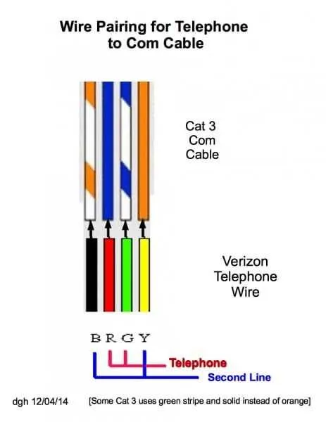
For successful restoration or troubleshooting of vintage communication networks, refer to the classic multi-pair cable color code: red and green form the primary pair, with yellow and black serving as the secondary. Confirm continuity by testing resistance between these pairs before proceeding with repairs.
Key wiring conventions include the use of twisted pairs to minimize interference. The red conductor typically carries the positive line, while the green is negative. Proper identification of each strand ensures accurate reconnection and prevents cross-talk or signal loss.
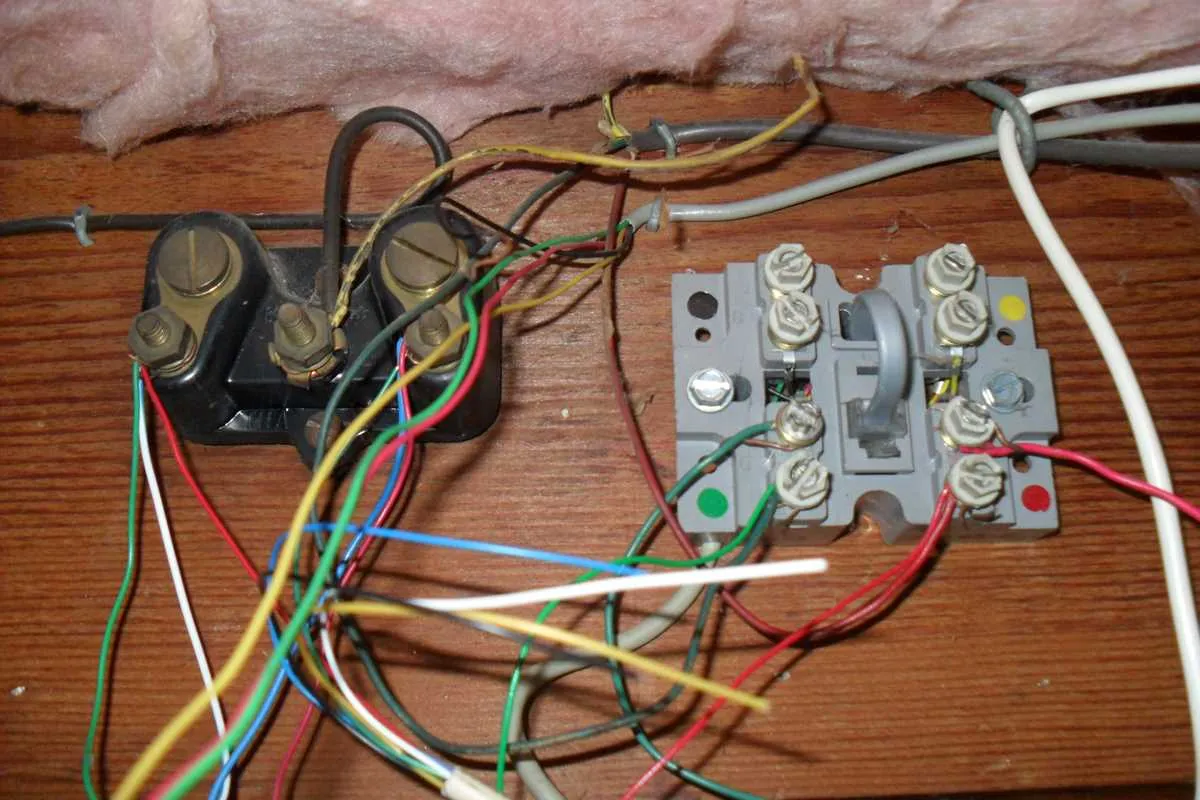
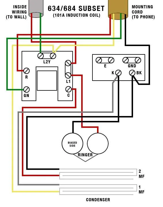
Mapping the circuit requires attention to junction blocks and terminal strips where wires converge. Document all connections carefully to maintain the original configuration or adapt it for modern compatibility. Using a tone generator can facilitate locating breaks or shorts in the cable run.
Legacy Landline Connection Layout

For traditional voice line installations, the standard cable consists of four conductors, typically arranged in pairs: red and green for the primary line, and yellow and black for a secondary line. The main pair (red/green) carries the active signal, while the others remain unused unless multiple lines are present.
Connection points usually follow the Bell System color code. The red wire connects to the “tip,” and the green wire to the “ring,” forming the basic circuit. When troubleshooting, ensure the red and green leads maintain continuity from the network interface to the handset socket without corrosion or breaks.
Older setups often rely on a single pair twisted cable, but some systems utilize a four-wire format to support additional extensions or devices like fax machines and modems. When extending or repairing, match the wire colors exactly to avoid cross-talk or signal loss.
Test the cable pairs with a simple continuity tester or multimeter, confirming no shorts or open circuits between the designated leads. Proper insulation and secure terminal connections at junction boxes prevent interference and maintain call clarity.
Replacing components demands adherence to the original layout to maintain compatibility with legacy switching equipment. Use screw terminals or punch-down blocks compatible with the existing infrastructure to secure the conductors firmly.
Identifying Wire Colors and Their Functions in Vintage Communication Systems

Refer to these color codes to accurately determine the purpose of each conductor in legacy voice circuits:
- Red: Typically carries the positive voltage (Tip) of the main pair, serving as the primary line conductor.
- Green: Acts as the negative voltage conductor (Ring), completing the pair for signal transmission.
- Yellow: Often used as the first auxiliary line or a secondary circuit conductor.
- Black: Commonly assigned to ground or common return paths in multi-line setups.
- White: Sometimes serves as an alternate Tip conductor or control wire depending on installation specifics.
- Slate (Gray): Usually reserved for an alternate Ring conductor or additional signal line.
For multi-pair cables, colors follow a systematic pattern derived from the Bell System standard, combining primary colors (red, green, yellow, black, white) with secondary stripes to differentiate pairs.
- First pair: Red (Tip) and Green (Ring)
- Second pair: Yellow (Tip) and Black (Ring)
- Third pair: White (Tip) and Slate (Ring)
- Subsequent pairs add stripes matching this order to the base color
When working with legacy setups, always verify continuity and signal direction using a multimeter or a line tester to avoid confusion caused by color fading or non-standard modifications.
Step-by-Step Connection Guide for Installing Vintage Phone Lines
Begin by turning off all power sources linked to the communication system to prevent shorts or shocks. Identify the main junction box where the external line enters the building. Use a multimeter to verify there is no voltage.
Strip about 1/2 inch of insulation from each conductor using wire strippers. Match the color codes: typically, red and green wires carry the primary pair, while yellow and black serve as secondary or grounding conductors.
Connect the red wire to the ring terminal and the green wire to the tip terminal on the connector block or mounting terminal strip. Ensure firm contact by tightening screws securely without damaging the wire.
If the setup includes a grounding wire, attach the black conductor to the grounding screw or bus bar inside the distribution panel to minimize interference and static.
Route cables neatly along walls or inside conduits, avoiding sharp bends and contact with electrical lines to prevent crosstalk or damage. Secure cables with clips or ties every 12 to 18 inches.
Use a butt splice or insulation displacement connectors for joining cables in-line, ensuring insulation is intact to avoid corrosion. Avoid twisting wires excessively.
After all connections, test the circuit with a line tester or phone device to confirm a clear dial tone and proper signal transmission. Troubleshoot any dead spots by rechecking terminations and continuity.
Finally, label each pair clearly at junction points and terminal strips for future maintenance or upgrades. Maintain documentation with color codes and routing paths for reference.
Troubleshooting Common Issues in Legacy Communication Line Setups
Start by checking continuity with a multimeter across the pair of copper conductors; breaks or high resistance often cause signal loss or static. Ensure insulation remains intact to avoid shorts between conductors, especially where cables run through damp or corrosive environments.
Verify that connectors and terminals are free of corrosion. Oxidation on metal contacts frequently leads to intermittent connections or complete line failure. Cleaning with isopropyl alcohol and reseating connections can restore proper function.
Crossed or reversed pairs disrupt signaling and can cause no dial tone or call drops. Confirm correct color coding per original layout standards: typically, red and green wires form the primary pair, with yellow and black as secondary pairs. Mismatches must be corrected.
Look for physical damage caused by rodents or mechanical stress, such as crushed or kinked cables. Replace damaged sections to maintain signal integrity and avoid noise interference.
Test for voltage presence on the line with a voltmeter. Lack of the standard 48V DC from the central exchange side indicates upstream supply issues, which must be addressed before local troubleshooting.
Grounding faults can induce hum or buzz on the line. Inspect grounding points and ensure that shielding or drain wires are properly connected to a reliable earth ground.