
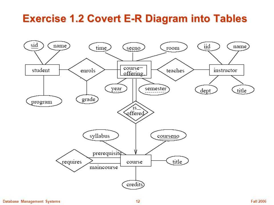
An ER diagram, also known as an Entity-Relationship diagram, is a visual representation of the relationships between entities in a database. It helps to organize and understand the various data elements and their relationships within a system. Converting an ER diagram into tables is an important step in designing a database structure.
During the conversion process, each entity in the ER diagram is turned into a table, with each attribute becoming a column. The relationships between entities are represented by foreign keys, which are used to link the tables together. This conversion process helps to ensure that the database is structured efficiently and accurately represents the data model.
Converting an ER diagram to tables can be done using various software tools, including PowerPoint (PPT). By creating a PowerPoint presentation, you can visually represent the conversion process, making it easier to communicate and present the database design to stakeholders.
In the PowerPoint presentation, you can use slides to represent each entity and its attributes, showcasing how they are transformed into tables. You can also use animations and transitions to demonstrate the relationships between entities and how foreign keys are used to create connections between tables.
Overall, converting an ER diagram to tables using a PowerPoint presentation can be an effective way to communicate and visualize the database design process. It helps to ensure that all stakeholders have a clear understanding of the relationships between entities and how the data is structured within the system.
Understanding ER diagrams
An Entity-Relationship (ER) diagram is a visual representation of the relationships between entities in a database. It is used to model and design a database schema, showing the logical structure of the data and how the entities are related to each other. ER diagrams are an essential tool for database developers and administrators.
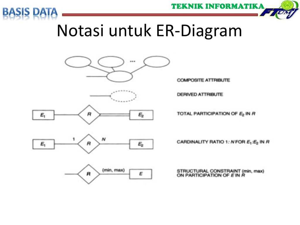
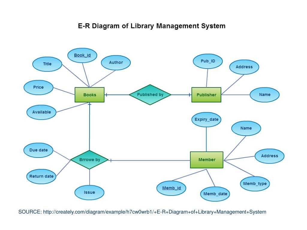
In an ER diagram, entities are represented as rectangles, and relationships between entities are represented as lines connecting the rectangles. Each entity has attributes, which are the properties or characteristics of the entity. These attributes are listed inside the rectangle representing the entity.
The relationships between entities can be of different types, such as one-to-one, one-to-many, or many-to-many. This information is displayed using different symbols and line styles in the ER diagram. For example, a one-to-many relationship is represented by a solid line with a crow’s foot notation on the side of the “one” entity, indicating that it can have multiple connections to the “many” entity.
An ER diagram provides a visual representation of the database schema, making it easier to understand and communicate the relationships between entities. It can also be used as a blueprint for creating the actual database tables and their relationships. By analyzing the ER diagram, database developers can determine the necessary tables, their attributes, and the primary and foreign keys needed to establish the relationships.
Key concepts in ER diagrams:
- Entities: Represented as rectangles, entities are the objects or concepts in the database that the system stores information about.
- Attributes: Describes the properties or characteristics of an entity.
- Relationships: Connections between entities that define how they are related to each other.
- Primary Key: A unique identifier for each entity, used to uniquely identify records in a table.
- Foreign Key: A field in one table that refers to the primary key of another table, establishing a relationship between the two tables.
Importance of converting ER diagrams to tables
The process of converting entity-relationship (ER) diagrams to tables is a crucial step in database design and management. ER diagrams provide a visual representation of the relationships between different entities in a database, while tables serve as the actual storage structure for the data. By converting ER diagrams to tables, various benefits can be realized.
1. Structured data representation: Converting ER diagrams to tables helps in organizing and structuring data in a systematic manner. Each table represents a specific entity, and the columns within the table correspond to the attributes or properties of that entity. This structured representation allows for efficient storage and retrieval of data, making it easier to manage and maintain the database.
2. Relationship representation: ER diagrams represent the relationships between entities using various types of connectors, such as one-to-one, one-to-many, or many-to-many. By converting these relationships into foreign keys in the tables, the actual connections between the entities can be established. This allows for the enforcement of data integrity and facilitates the retrieval of related data in a meaningful way.
3. Improved database performance: Converting ER diagrams to tables can contribute to improved database performance. By properly defining the data types, constraints, and indexes on the table columns, the database engine can optimize the storage and retrieval of data. This leads to faster query execution and improved overall performance of the database system.
4. Simplified data management: Converting ER diagrams to tables simplifies the process of data management. Each table represents a distinct entity or concept, and the attributes associated with that entity are stored within the corresponding columns. This organized structure makes it easier to add, update, or delete data in the database, as well as to perform complex queries and generate meaningful reports.
In conclusion, converting ER diagrams to tables is essential for effective database design and management. It provides a structured representation of data, establishes relationships between entities, improves database performance, and simplifies data management tasks. By leveraging the power of tables, businesses can efficiently store, retrieve, and manipulate their data, leading to better decision-making and improved productivity.
Step-by-step process of converting ER diagrams to tables
Converting ER diagrams to tables is an essential step in the process of designing a relational database. It involves transforming the entities, relationships, and attributes represented in the ER diagram into corresponding tables, columns, and foreign key constraints in a relational database.
Here is a step-by-step process to guide you through the conversion of ER diagrams to tables:
- Identify entities: The first step is to identify the entities in the ER diagram. Entities represent real-world objects or concepts that need to be stored in the database. For example, in a university database, entities could include students, courses, and professors.
- Create tables: Once the entities are identified, create tables for each entity in the ER diagram. Each table represents an entity and should have a unique name and a primary key column to uniquely identify each row. For example, a “Students” table might have columns like “student_id”, “first_name”, “last_name”, and “email”.
- Identify relationships: Next, identify the relationships between entities in the ER diagram. Relationships represent how the entities are associated with each other. For example, a student can be enrolled in multiple courses, which establishes a relationship between the “Students” and “Courses” entities.
- Create foreign keys: To represent relationships between tables, create foreign key columns in the tables that correspond to the primary key column of the related table. Foreign keys establish the relationships between entities in the database. For example, in the “Courses” table, there can be a foreign key column like “student_id” to track which student is enrolled in the course.
- Add attributes: Finally, add attributes to each table based on the attributes identified in the ER diagram. Attributes represent the properties or characteristics of the entities. For example, the “Students” table can have attributes like “date_of_birth” and “major”.
By following these steps, you can successfully convert an ER diagram into a set of tables that form the foundation of a relational database.
Challenges in converting ER diagrams to tables
Converting an ER diagram into a set of tables can be a complex process that requires careful consideration of various factors. Here are some of the challenges that can arise during this conversion:
- Entity identification: One of the main challenges is accurately identifying the entities and their attributes from the ER diagram. An entity may have multiple attributes, including composite attributes and multi-valued attributes, which need to be correctly represented in the table structure.
- Relationship representation: Another challenge is representing relationships between entities in the table structure. Depending on the cardinality and type of relationship (one-to-one, one-to-many, many-to-many), different strategies such as foreign keys or junction tables may need to be used.
- Normalization: Normalizing the table structure is an important consideration in the conversion process. Ensuring that the tables are in the appropriate normal form and minimizing redundancy and dependency issues can be challenging and time-consuming.
- Data integrity: Maintaining data integrity is crucial when converting ER diagrams to tables. Constraints and rules need to be properly defined and implemented to ensure that the data stored in the tables is accurate, consistent, and complies with the intended business rules.
- Data type mapping: Mapping data types between the ER diagram and the table structure can be a challenging task. Ensuring that the data types used in the tables align with the expected data types for the attributes can help prevent data quality issues and improve performance.
Overall, converting ER diagrams to tables requires careful analysis, attention to detail, and a solid understanding of database design principles. It is important to address these challenges effectively to ensure the successful transformation of the conceptual model into a physical database schema.
Best Practices for Converting ER Diagrams to Tables
Converting ER diagrams to tables is a crucial step in the database design process. It ensures that the data model accurately represents the relationships between entities and attributes. However, this process can be complex and prone to errors if not approached carefully. Here are some best practices to consider when converting ER diagrams to tables:
1. Understand the ER Diagram
Before starting the conversion process, it is important to thoroughly understand the ER diagram. This includes understanding the entities, attributes, relationships, and cardinalities. Having a clear understanding of the ER diagram ensures that the resulting tables accurately capture the intended structure and relationships.
2. Normalize the Data Model
Normalization is the process of organizing data in a database to reduce redundancy and improve data integrity. It is important to apply normalization techniques when converting ER diagrams to tables. This includes identifying and removing redundant data by creating separate tables for related entities and establishing appropriate relationships between them.
3. Choose Appropriate Data Types
When converting attributes from the ER diagram to table columns, it is crucial to choose appropriate data types for each attribute. This ensures that the table can accurately store and represent the data. Consider the size, range, and nature of the data when selecting data types.
4. Define Primary and Foreign Keys
In the process of converting ER diagrams to tables, it is important to define primary and foreign keys. Primary keys uniquely identify each record in a table, while foreign keys establish relationships between tables. This helps maintain data integrity and enables efficient data retrieval.
5. Consider Performance and Scalability
When converting ER diagrams to tables, it is important to consider performance and scalability. This includes optimizing table structures, indexing columns for faster data retrieval, and partitioning large tables to improve query performance. Designing tables with performance and scalability in mind ensures that the database can handle increasing amounts of data and user activity.
6. Document the Conversion Process
Lastly, it is important to document the conversion process. This includes keeping track of the decisions made during the conversion, documenting any changes or modifications, and providing clear and concise documentation for future reference. This helps maintain the integrity of the data model and facilitates collaboration among team members.
Overall, converting ER diagrams to tables requires careful consideration and adherence to best practices. By understanding the ER diagram, normalizing the data model, choosing appropriate data types, defining keys, considering performance and scalability, and documenting the conversion process, you can create a robust and efficient database structure.
Q&A:
What is the first step in converting an ER diagram to tables?
The first step in converting an ER diagram to tables is to identify the entities and their attributes in the diagram. This is done by examining the entity shapes and noting down the attributes specified within them.
How do you convert relationships in an ER diagram to tables?
To convert relationships in an ER diagram to tables, you need to examine the relationship lines and identify the cardinality and participation constraints. These constraints will determine whether a foreign key is needed in one of the tables to represent the relationship.
What are the best practices for naming tables in a database?
When naming tables in a database, it is best to use descriptive and meaningful names. Avoid using abbreviations or acronyms that may not be clear to other users. Additionally, it is recommended to use singular nouns for table names to maintain consistency.
How do you handle attributes with multiple values in an ER diagram?
Attributes with multiple values in an ER diagram can be handled by creating a separate table to represent the attribute. This table will have a foreign key that references the primary key of the entity the attribute belongs to. Each value will then be stored as a separate row in the attribute table.
What is the purpose of primary keys in database tables?
The primary key in a database table serves as a unique identifier for each record in the table. It ensures data integrity by enforcing entity integrity constraints, preventing duplicate or null values in the key column. Primary keys are used for data retrieval, joining tables, and maintaining relationships between tables.
What are the best practices for converting ER diagrams to tables?
Some best practices for converting ER diagrams to tables include clearly defining entities and their relationships, accurately mapping attributes to columns, setting primary keys and foreign keys, normalizing the tables to eliminate redundancy, and properly documenting the database schema.
Why is it important to properly convert ER diagrams to tables?
It is important to properly convert ER diagrams to tables as it ensures that the database accurately reflects the structure and relationships of the entities. By following best practices, it helps to maintain data integrity, optimize query performance, and facilitate future database maintenance and modifications.