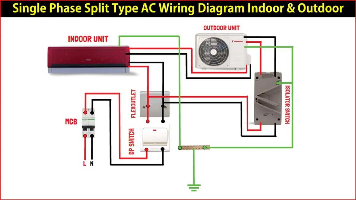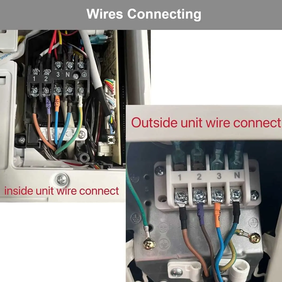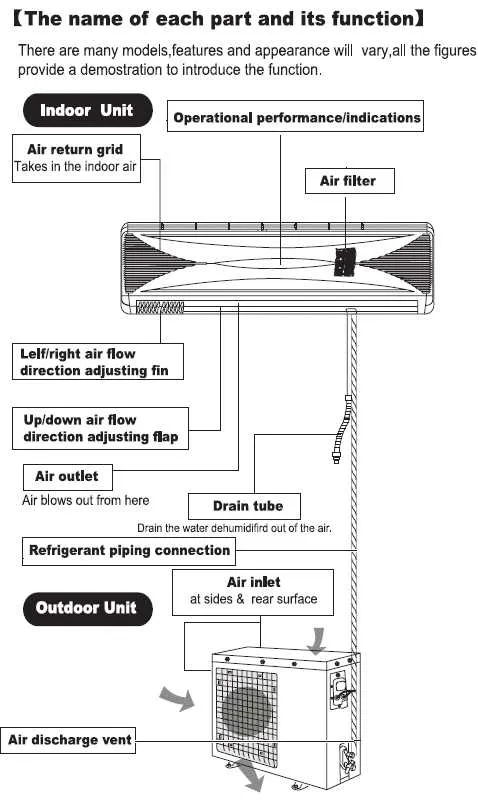
When installing a ductless air conditioning system, understanding the connection points and electrical setup is crucial for efficient and safe operation. Ensure that all electrical connections follow the manufacturer’s specifications and local building codes to prevent electrical issues and ensure optimal performance.
First, pay close attention to the power supply. Your system should be connected to a dedicated circuit with the appropriate voltage and amperage to handle the load. A high-quality breaker with the correct rating will protect both your unit and your home’s electrical infrastructure from potential hazards.
Next, focus on the interconnecting cable between the indoor and outdoor units. This wiring carries signals and power for the system to function properly. It must be shielded and capable of withstanding outdoor conditions to avoid damage. Additionally, check for a stable and secure mounting of the cable to prevent accidental disconnections.
Finally, verify all grounding and safety connections. Grounding is essential to protect your equipment from electrical surges and faults. A proper earth connection ensures that any excess electrical current is safely directed away from the system, reducing the risk of malfunctions or damage to internal components.
Electrical Connections for Ductless AC Systems

To ensure proper functionality of your ductless air conditioning unit, focus on the correct power supply and signal connections. Start by connecting the outdoor unit to the power source. Use a dedicated circuit breaker rated for the unit’s power requirements, typically 15 or 20 amps. The voltage should match the system specifications, which are usually 220V or 240V in residential setups.
The connection between the indoor and outdoor units relies on a communication cable, typically 4 or 5 core. This cable must be run through a conduit to protect it from environmental factors. Ensure the wiring is securely fastened and free from any sharp bends that could cause damage to the insulation.
For the power supply to the indoor unit, use a 14 AWG wire for standard installations, ensuring the wire length does not exceed 50 feet to avoid voltage drop. A separate power supply line is necessary for the cooling unit, as it requires a continuous, reliable power source.
Always use the correct size of the electrical connector to match the wire gauge. This prevents overheating, which could result in system failure. Make sure to follow the manufacturer’s recommendations for grounding the system to avoid electric shock hazards.
Before completing the setup, double-check that all wires are firmly connected and that there is no exposed copper. Insulate connections properly to avoid short circuits or accidental contact. Once installed, confirm that the unit starts up correctly and that there is no unusual noise or heating of the cables.
Understanding the Power Supply Setup for Air Conditioning Systems

Ensure that the power supply meets the requirements specified by the manufacturer. Most systems operate on a 220-240V single-phase or 380-415V three-phase current. Check the voltage rating on the unit’s nameplate before proceeding with installation.
Disconnecting the power source before starting any installation or maintenance work is crucial for safety. Use a dedicated circuit with proper grounding to avoid electrical hazards.
Install a circuit breaker with appropriate amperage, typically 15-20A for smaller units and 30-40A for larger ones. The breaker should be placed in close proximity to the unit for easy access in case of an emergency.
Double-check the conductor size based on the unit’s power demand. For a typical 1.5-ton system, use a 14 AWG wire for a 15A circuit; for a larger unit, increase the wire size accordingly. Correct wire gauge prevents overheating and ensures proper current flow.
Connect the power lines to the designated terminals, typically labeled L1 (live), L2 (neutral), and ground. Confirm the integrity of each connection to avoid electrical faults.
Lastly, always verify the earth ground connection before powering up the system. A poor ground can lead to electrical shocks or damage to the internal components of the system.
Connecting the Thermostat and Control Wiring in Ductless AC Systems
Ensure the thermostat is placed in a location with accurate room temperature readings, away from direct sunlight or air drafts. Connect the control cables from the unit’s central control board to the thermostat terminals. The common terminal (C) should be linked to the appropriate contact on the thermostat to provide continuous power. Attach the heating or cooling signal wires to the corresponding terminals–these typically include a heat (H) or cooling (C) mode connection. For cooling mode, ensure the “cool” signal wire is connected securely to both the indoor and outdoor units’ main boards.
Use low-voltage cables, typically 18 to 22 AWG, to connect the control panel and the thermostat. Ensure a solid, clean connection to avoid any issues with weak signals or miscommunication between the components. Be sure to use the correct polarity for the power wires, as reversing them could lead to improper operation of the system.
Test the connection by turning the system on and setting the desired temperature on the thermostat. The unit should respond accordingly by adjusting the internal fan speed, cooling, or heating settings. If the system doesn’t respond as expected, double-check the wire connections and ensure the thermostat is calibrated correctly for the type of system in use.
Common Troubleshooting Steps for Electrical Issues in Ductless AC Systems
If the system isn’t turning on or is malfunctioning, check the power supply and connections first.
- Verify that the main power switch is in the “ON” position.
- Ensure the fuse or circuit breaker hasn’t tripped and that the electrical panel is intact.
- Inspect the power cord and plug for any visible damage or signs of wear.
If the unit powers on but fails to function correctly, proceed with the following checks:
- Check the internal connections of the control board for loose terminals or corroded connectors.
- Ensure the remote control or thermostat is correctly paired with the unit.
- Confirm that the indoor and outdoor units are properly linked to each other through the electrical setup.
If the system works intermittently, inspect the following:
- Look for overheating or burning smells near electrical components.
- Verify that all connections are tight and secure, with no exposed wires that could cause short circuits.
- Check for faulty sensors or damaged circuit boards that may lead to unstable operations.
For persistent issues, a multimeter can be used to measure voltage and continuity in key components, such as:
- The compressor motor wiring.
- The relay contacts within the control panel.
- Power supply terminals for correct voltage output.
If troubleshooting reveals damaged or malfunctioning parts, replacement is necessary to restore proper function. Always follow manufacturer guidelines when performing repairs or replacements.