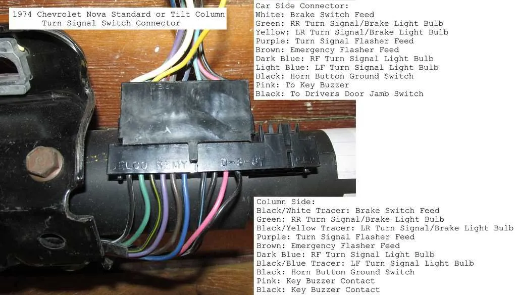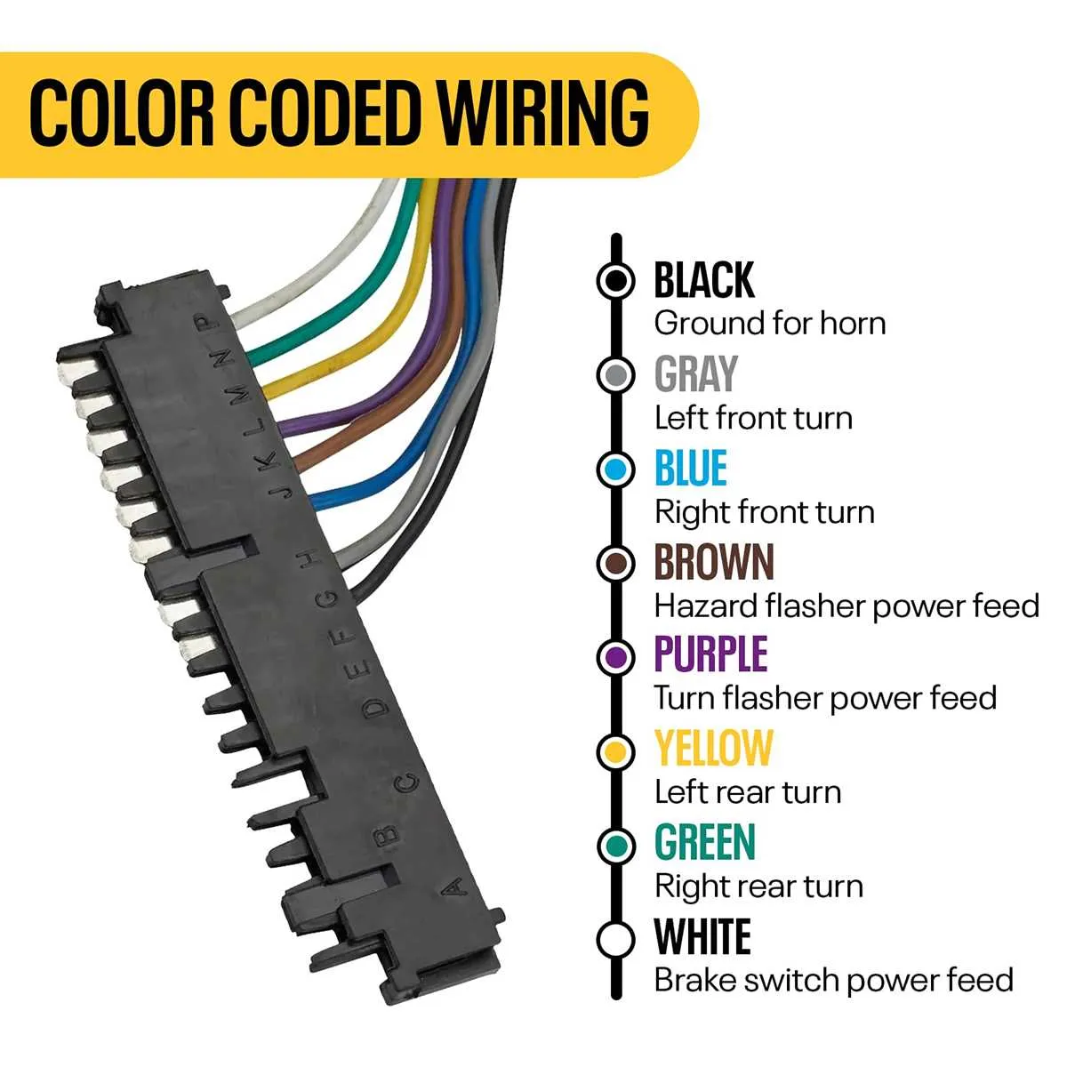
If you’re working on a GM vehicle’s control assembly, the following setup guide will help you connect the key components. Ensure you follow the specific wire-to-terminal assignments to avoid faulty connections.
Pin 1 should be connected to the ignition switch, which sends the signal to the control system. This will activate the main functions, such as wheel position adjustment.
Pin 2 links to the turn signal module, which manages left and right directional signals. Pay close attention to the wire’s color and position for proper functionality.
Pin 3 controls the horn circuit. It’s essential that this connection is secure, as a loose wire could lead to malfunctioning or failure of the horn when activated.
Pin 4 handles the connection to the airbag system. Improper installation could trigger safety concerns, so make sure this link is firmly established.
Check for any corrosion or wear on the connectors before installation. An unreliable connection can cause the system to underperform or fail to operate at all. Always refer to the vehicle’s specific manual for any further details or updates.
GM Wiring for Control Components

Start by matching the wire colors to the appropriate functions in the control assembly. The following guide provides a clear overview of common wire assignments found in GM models. Ensure the connections are properly insulated to prevent any short circuits.
The red wire typically supplies power, and it is essential for the activation of key components. The black wire is the ground connection, which helps maintain a safe electrical flow. For the signal, look for the yellow or green wire–these often carry important signals for the ignition or horn system.
For the turn indicator system, a blue or orange wire usually handles the left and right signals, while a brown wire is often associated with the hazard lights. Check the wiring harness for these specific colors to avoid mixing up connections.
In certain models, the white wire could serve as the link for the cruise control system or other advanced functions. It’s crucial to verify its exact purpose in the specific year and model of your vehicle.
Finally, when replacing or repairing, always double-check that the wire connections are firmly secured and correctly routed to maintain vehicle safety and electrical integrity.
How to Identify Wire Colors in GM Steering Column Wiring
To correctly identify wires in the GM steering mechanism, start by referring to the vehicle’s manual or specific repair guide for your model. The first step is to understand the basic function of each wire. Typically, the primary wires are linked to key systems like ignition, turn signals, and cruise control.
Use a multimeter to test for continuity between terminals. This will help ensure you have a correct match when tracing each lead. For example, a red wire is often associated with power, while black is commonly ground. Green and yellow wires are typically linked to signal functions.
Additionally, check for markings on the wire itself. Many GM vehicles use small, numbered tags or letters to indicate which function each wire serves. If no such markings exist, testing with a voltage meter or circuit tester will be crucial.
If working with older vehicles or wiring without visible identification, documenting each wire’s location and corresponding function during disassembly is essential. This can save time when reassembling or troubleshooting.
Step-by-Step Guide to Wiring GM Steering Column Components
Start by disconnecting the vehicle’s battery to ensure safety during the installation. Locate the main harness that feeds into the steering assembly and strip back the protective covering carefully to expose the individual wires.
Identify each wire according to its function. Typically, you’ll find wires for the turn signal, horn, ignition, and lighting. For accurate connections, verify the function of each wire using a multimeter or reference manual for specific vehicles.
When connecting wires, ensure that each is securely fastened and properly insulated. Use crimp connectors or solder the ends of wires where needed, ensuring no exposed metal parts can cause short circuits.
For the ignition system, connect the power wire to the ignition switch, making sure it’s routed properly to avoid any interference with the driver’s operation. Follow the vehicle’s manual for the exact placement of each wire relative to other components.
For the turn signal and horn, connect their respective wires to the appropriate switch terminals on the assembly. Make sure the wires are cleanly stripped and firmly attached to prevent loosening over time.
Once all connections are made, test each component individually. Turn the ignition key to the “on” position and check the functionality of the horn, turn signals, and any other system linked to the wiring setup.
Finally, securely attach the assembly back into place, ensuring no wires are pinched or at risk of being damaged during reassembly. Reconnect the vehicle battery and verify that all systems are operational.
Common Issues with GM Steering Column Wiring and How to Fix Them
If your vehicle is experiencing electrical issues in the wheel area, it’s often related to faulty connections or worn-out components. Here are the most common problems and ways to address them:
- Faulty Horn Connection: The horn may fail due to a broken or loose contact in the electrical connectors. Check the connection under the dashboard for wear or corrosion. To fix this, clean the terminals or replace the damaged connector.
- Malfunctioning Turn Signals: A common issue is the turn signal not working properly, which could be caused by a damaged wire or poor contact in the switch. Inspect the switch and wiring for signs of wear or breaks. If the switch is faulty, replace it, ensuring the wiring is intact and secure.
- Non-Functional Cruise Control: If the cruise control isn’t activating, the issue may be with the circuit that connects to the control buttons on the wheel. Check the wire connections to the buttons and ensure the signal is being transmitted properly. Replace any broken connections or corroded components.
- Airbag Issues: A common concern in older vehicles is airbag failure due to poor wiring or damaged connectors. Always ensure that the wiring beneath the airbag cover is intact. If you find any damage, have it repaired immediately to avoid safety risks.
- Loss of Power to Accessories: If the controls for your lights or other accessories stop functioning, inspect the connection points for loose or frayed cables. Replace or reattach any loose wires and check the fuse box for any blown fuses that may be disrupting the flow.
By carefully inspecting these components and replacing or repairing faulty parts, you can restore functionality to the electrical systems in the wheel area without much hassle.