Recommended Cable Setup
Use a three-port module system for optimal performance. Connect the control harness (26345) directly to the joystick or handheld controller. Ensure the power cable (63411) connects from the battery to the isolation module. Ground connections must be securely fastened to the vehicle chassis, avoiding painted surfaces for clean contact.
Main Electrical Components
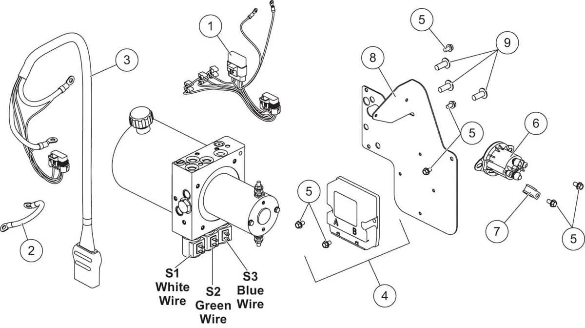
- Module: Isolation type, three-port (part 29070), handles signal distribution.
- Control Harness: Part 26345, links controller to module.
- Headlamp Harness: Vehicle-specific; verify compatibility before installation.
- Power Cable: Heavy gauge (part 63411), connects battery to module and hydraulic unit.
Step-by-Step Setup

- Attach battery cable (positive) to module; use included fuse holder.
- Secure ground lead directly to vehicle frame, avoiding any corrosion or coatings.
- Connect control harness from cabin controller to module; verify all pins align.
- Link vehicle headlamp adapter to module; confirm correct side orientation (left/right).
- Connect hydraulic unit power lead (positive) to module; tighten all terminals firmly.
- Test connections using controller: check lift, angle, and light functions.
Troubleshooting Tips

If controls are unresponsive, inspect ground connection and ensure no corrosion. Verify fuse integrity on the positive power cable. Double-check all module ports for secure and proper alignment. For lighting issues, confirm headlamp harness matches vehicle model and no pins are bent.
Always refer to the specific part numbers and technical manuals to ensure accurate assembly and avoid damage to electrical systems.
Minute Mount 2 Electrical Layout Details
Begin by verifying the three-port isolation module connections: Port 1 links to the control harness, Port 2 connects to the vehicle harness, and Port 3 leads to the front harness. Ensure all pins are seated firmly to avoid intermittent faults.
Next, check the solenoid valve coil terminals. Use a multimeter to confirm 12V is supplied when the joystick or handheld controller commands lift, left, or right movement. A missing signal indicates a broken circuit or faulty controller output.
Inspect the vehicle’s headlamp adapter plugs. For setups using HB3/HB4 bulbs, ensure the left and right adapters match the truck’s OEM connectors. Misaligned adapters cause lighting malfunctions or back-feeding current.
Battery power routes through the primary red cable, protected by a 2-amp fuse near the control harness. Confirm the fuse integrity with a continuity tester; replace if blown. Double-check the black ground lead’s connection to a clean, corrosion-free chassis point.
Test the motor relay (solenoid) by measuring voltage at the small trigger terminal when the controller activates the lift function. If no voltage is present, trace back to the control module’s output pin. If voltage is present but the motor does not spin, suspect a defective relay or corroded high-amperage connections.
Check the controller’s backlight and indicator LEDs. If these fail to illuminate, inspect the orange accessory wire, which must have 12V ignition-switched power. Without this feed, the controller remains inactive despite correct power and ground at the main leads.
Lastly, validate the ground path from the controller to the chassis. Poor grounding often leads to erratic behavior, such as slow response or non-functioning hydraulic controls. Run a dedicated ground jumper if necessary to bypass rusted or painted surfaces.