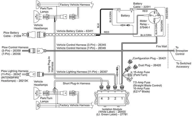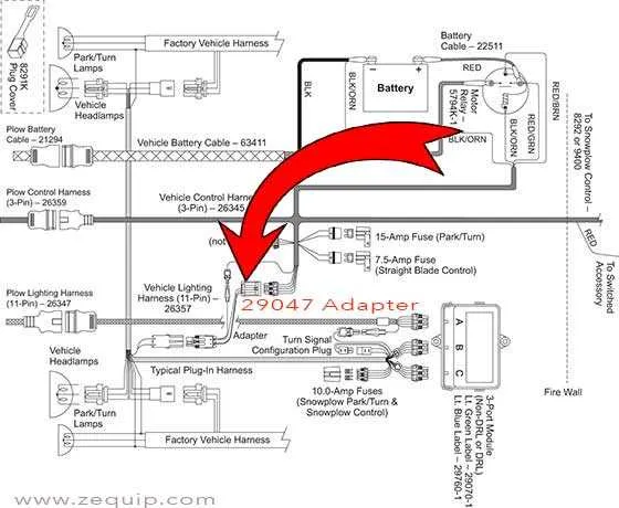
To ensure optimal performance and safe operation of your snow removal machine, proper connection and layout of the electrical components are crucial. Begin by identifying the key elements involved in the system: the motor, control unit, and power supply lines. Each component should be clearly connected according to the manufacturer’s instructions to avoid malfunction or damage during use.
First, check the main power supply, ensuring that it’s securely linked to the system’s central control mechanism. Use high-quality connectors and cables that can withstand cold temperatures and resist corrosion. Pay special attention to the wire gauge, as using an undersized wire could lead to overheating and potential failure.
Next, ensure that the switchboard and relay connections are positioned correctly to enable immediate response times. Incorrectly placed or poorly connected relays could lead to delays in activation or malfunction. Always verify continuity with a multimeter before proceeding with the setup to confirm each connection is intact and properly grounded.
Finally, refer to the detailed schematic for pinouts and connections of the various sensors and safety mechanisms. These components play a vital role in controlling the functionality of the machine, ensuring that it responds appropriately to commands, such as raising or lowering the blade. Proper integration of all elements will ensure efficient and safe operation in challenging conditions.
Electrical Connections for Snowplow Systems
Ensure proper operation of your snow removal system by following these key connection guidelines:
- Confirm the power source is securely linked to the main control unit.
- Check that all terminals are clean and corrosion-free for effective contact.
- Verify the ground connections to avoid electrical faults during operation.
- Inspect the switch terminals, ensuring they are properly sealed to prevent moisture ingress.
To troubleshoot issues, follow these steps:
- Test each connection with a multimeter to confirm voltage is reaching the control module.
- Examine the wiring paths for potential frays or breaks, particularly around the pivoting sections.
- If the system isn’t responding, consider checking the fuses for signs of damage.
- For hydraulic or electrical malfunctions, consult the manual for specific troubleshooting steps.
Always use waterproof connectors and ensure that the wiring is routed away from sharp edges to prevent wear and short circuits. Periodically recheck connections during the season to maintain system reliability.
Understanding the Basic Electrical Layout
To effectively set up the electrical connections of your snow removal equipment, begin by identifying the key components involved in the system. These include the controller, solenoid, motor, and the power source. Proper installation starts with ensuring that the main power cable is securely connected to the battery. This cable typically runs directly to a fuse or circuit breaker for protection.
Next, focus on the switch mechanism or controller. It should be wired to a relay, which controls the solenoid that powers the lifting mechanism. The relay must be correctly connected to ensure that signals are transmitted smoothly from the controller to the solenoid, activating the motor as needed. Be sure to check the grounding connections for proper functionality, as a poor ground can cause the system to fail to operate efficiently.
Verify that all connectors are tightly secured and insulated to prevent any short circuits. Additionally, check the condition of the wires for wear and replace any damaged ones. For enhanced durability, use weather-resistant components to protect against environmental factors such as moisture and corrosion.
Finally, consult the equipment’s manual to confirm the wiring color codes and ensure that all connections are made according to the manufacturer’s specifications. This will help prevent any miswiring that could lead to operational issues or system failures.
Steps to Troubleshoot Common Electrical Issues

Begin by checking the main connection points for corrosion or wear. Clean any terminals or connectors that may show signs of dirt, rust, or damage. Ensure a solid connection between all parts, as a loose link can disrupt power flow.
Test the power source: Use a multimeter to check for consistent voltage coming from the main power unit. If the voltage fluctuates or is below the required level, replace the power source or fix the supply lines.
Inspect the control unit: Examine the control system for any signs of malfunction or faulty buttons. A malfunctioning switch could be the reason for non-responsiveness. If the buttons feel sticky or unresponsive, consider replacing them or cleaning the internal contacts.
Examine fuses: Verify that no fuse has blown. A simple continuity test using a multimeter will help you identify any failed components. Replace any damaged fuse with one that matches the exact rating for the system.
Look for short circuits: Carefully check the wiring for exposed cables or places where wires may be touching metal surfaces. Insulation damage is a common cause of electrical short circuits. Repair any damaged wires and ensure proper insulation.
Check relays and solenoids: Test each relay or solenoid to ensure they are functioning properly. A faulty relay can prevent the system from operating as intended. If necessary, swap with a known good relay to confirm functionality.
How to Properly Connect the Control System

Ensure a secure connection between the control unit and the actuator system by first checking the compatibility of the connectors. Use proper terminal connectors that fit tightly to avoid any loose connections that could cause malfunction. Tighten all connections firmly but avoid over-tightening, which may damage the wires or terminals.
Wire routing is critical to prevent any electrical interference or potential damage. Route the cables away from sharp edges and hot surfaces, and secure them with clamps or zip ties to avoid any shifting during operation. Always check that the wiring is free from any potential pinch points, such as door seals or moving parts.
Double-check polarity to ensure correct functionality. If the system uses a direct current setup, make sure that the positive and negative terminals are connected appropriately. Incorrect polarity can result in malfunction or damage to the electronic components.
Test before full operation after installation. Before fully engaging the system, conduct a preliminary test by powering it on and checking for any issues such as unusual noise or irregular movements. Ensure that all switches respond correctly to inputs, and the feedback is accurate.