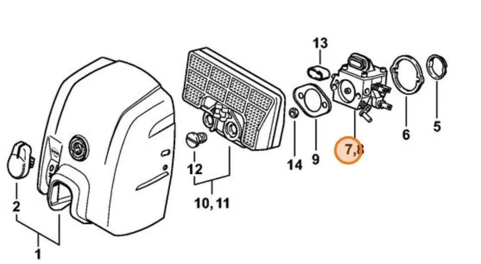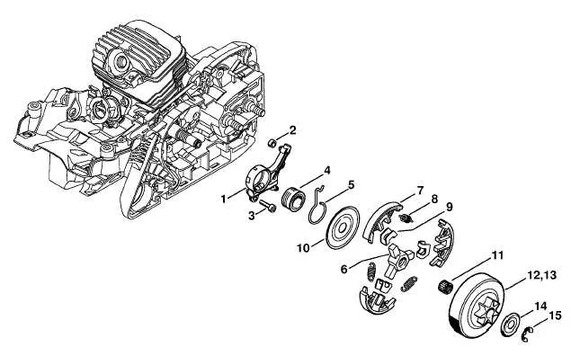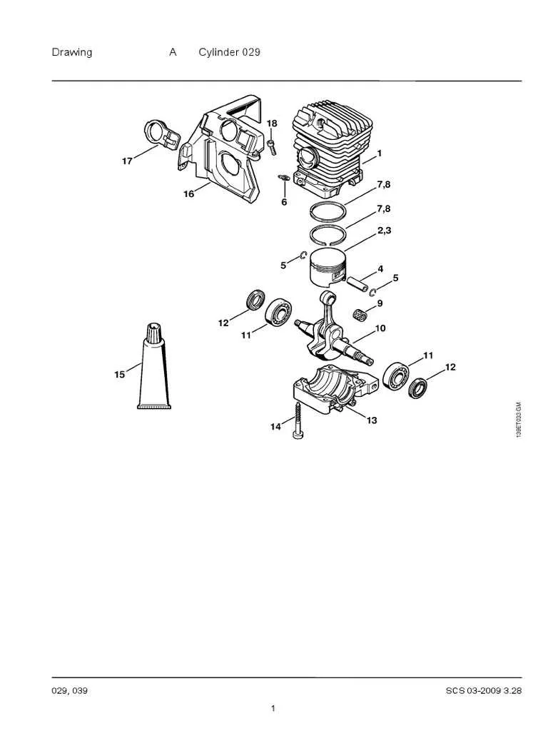
Refer to the comprehensive schematic to accurately identify individual elements of the cutting tool. This resource allows precise recognition of each mechanical unit, ensuring efficient maintenance and part replacement.
Key assemblies such as the engine housing, clutch mechanism, and chain tensioner are clearly illustrated to facilitate quick understanding of their arrangement and connection. Utilizing this layout minimizes errors during disassembly or reassembly.
Consulting this detailed layout is essential for both troubleshooting and routine upkeep, offering a clear path to locating specific hardware and preventing downtime caused by guesswork.
Component Layout for MS290 Chainsaw

Refer to the detailed schematic to identify each essential element accurately before disassembly or maintenance. Key assemblies such as the ignition system, carburetor, and chain brake are distinctly marked for easy recognition. Use the numbered illustration to locate small items like screws, washers, and springs, ensuring correct replacement and fit.
Focus on the crankcase and piston assembly sections to verify part orientation and alignment, crucial for optimal engine performance. The guide clarifies the positioning of oil pump components and fuel lines, helping prevent leaks and operational issues.
For ordering or repair, reference the exploded view to cross-check individual components, avoiding mismatched or incompatible substitutes. The layout also highlights wear-prone items, suggesting preemptive inspection to extend service intervals.
Locating Key Components in the Diagram
Start by identifying the engine block outline as the central reference point. From there, trace the fuel system components, which are usually positioned near the carburetor section marked with numbers corresponding to the intake assembly. Look for the ignition module symbol close to the flywheel illustration, often highlighted for easy identification.
The chain brake assembly is typically shown adjacent to the handle area, distinct by its linkage and spring details. The muffler and exhaust parts are located on the side opposite the carburetor, often annotated with smaller part numbers for precise matching.
Focus on the lubrication elements next–these are generally indicated around the oil pump and delivery tube, situated near the crankcase. The starter mechanism components appear grouped near the recoil assembly, characterized by coiled springs and pull handles.
Fasteners and small connectors are scattered throughout but usually cluster around major assemblies like the clutch and sprocket. Use the reference key included in the schematic to cross-check part codes, ensuring accurate pinpointing without confusion.
Interpreting Part Numbers and Labels

When deciphering the identification system for components, always focus on the alphanumeric code printed on the label. These numbers are crucial for accurate replacements and maintenance. Here’s how to break them down:
- Prefix Letters: Often indicate the category or group of the component. For example, ‘A’ might refer to accessories, while ‘B’ can denote a specific series or model version.
- Numeric Sequence: The series of numbers following the letters generally specifies the part’s unique identifier within the category. This sequence can often be cross-referenced with official manuals or catalogs for precise identification.
- Suffix Codes: These usually define the part’s specific version, color, or material used. Common suffixes include ‘X’, ‘V’, or a numerical suffix, which may indicate a revision or a version update.
Always compare the number on the label with the manufacturer’s catalog to confirm compatibility. If the label features multiple lines of text, they typically separate the part number from other details like batch codes or production dates.
- Batch Codes: These are often placed at the end of the label. They are used for manufacturing tracking and can help determine the exact production run.
- Serial Numbers: These follow the part number and are essential for warranty verification and tracking the part’s history. They can help identify specific batches that may have manufacturing defects.
Always ensure that the numbers and labels match the specifications for the intended replacement or repair. Any discrepancies could lead to issues with compatibility or performance.
Steps to Order Replacement Components Accurately

To ensure you receive the correct replacement elements for your equipment, start by identifying the specific model number of your device. Verify the serial number as well, which can often be found on the body or on a label located near the engine or control area. This information will help narrow down your search to the right components.
Next, refer to the manual or user guide for your device to locate the part numbers associated with the components you need. These are typically listed under maintenance or repair sections. If the manual is unavailable, many manufacturers provide digital copies on their official websites, often including diagrams for easy identification.
When placing your order, provide both the part number and the model details. Double-check for compatibility, especially if your equipment has undergone modifications. Some suppliers offer online tools that cross-reference part numbers and compatibility, making it easier to identify suitable options.
If you are uncertain about the required replacement, contact the supplier or service center directly with your model and serial number for clarification. They can assist in verifying the correct part selection, ensuring optimal performance and fit.