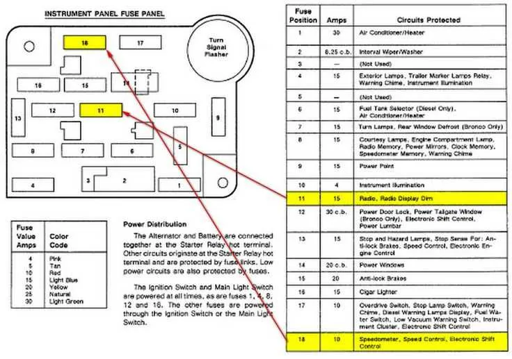
To effectively troubleshoot electrical issues in the 1995 model, start by checking the distribution panel for power sources. Ensure that each connection is secure, and the relevant terminals are intact. A thorough inspection of these components can prevent unnecessary replacements and help identify faulty connections quickly.
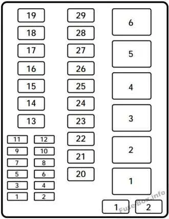
Focus on identifying the location of the relays and connectors controlling vital functions such as lighting, ignition, and accessories. These components are located in two main sections: the primary panel under the dashboard and the secondary unit near the engine bay. Both sections are crucial for the proper flow of electricity throughout the vehicle.
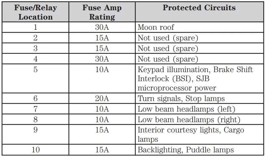
For optimal results, refer to the specific layout guide, which clearly indicates the location of each relay and fuse. Pay close attention to any blown components or signs of corrosion, which can interfere with the vehicle’s overall performance. If replacing any part, always use the specified ratings to avoid further electrical complications.
Additionally, always disconnect the battery before handling any electrical parts to minimize the risk of short circuits. If you’re unsure about handling these tasks, consulting a professional is advised, as improper installation can lead to further damage.
Electrical Component Layout for 1995 Pickup Truck
To troubleshoot electrical issues in your 1995 pickup, locate the control panel in the engine compartment and interior for precise connections.
- Under-hood panel: This unit contains critical relays and circuits for major functions like ignition and engine operation. Typically situated near the battery.
- Cabin unit: Found beneath the dashboard, near the driver’s side, housing circuits for lights, airbags, and interior accessories.
For a detailed map of each component:
- Engine control relay – essential for the starting system.
- Lighting circuits – ensure both external and interior illumination is functional.
- Radio power supply – for uninterrupted sound system operation.
- Wiper system – regulates front and rear windshield operation.
- ABS relay – crucial for braking system functionality in advanced models.
Checking connections: Regularly inspect for corrosion or loose terminals that may disrupt operation. A simple test light can identify faulty connections in both compartments.
Locating the Electrical Panel in the 95 Pickup

The main electrical control unit for the 1995 truck is located in two places: under the hood and inside the cabin. The under-hood unit can be found near the driver’s side, close to the front of the engine compartment, beside the battery. It’s protected by a plastic cover that can be removed by unclipping it. Inside the cabin, the unit is positioned beneath the dashboard, to the left of the steering wheel, near the kick panel. You may need to remove a panel or cover to access it.
If you’re searching for the one under the hood, check the area next to the battery and radiator for a rectangular compartment. The cabin unit can be accessed after removing the kick panel, which is typically held in place by screws or clips. Both locations provide direct access to the relays and connections you need for troubleshooting or repairs.
Understanding the Electrical Layout and Labeling

Ensure to familiarize yourself with the specific components outlined in the electrical layout of your vehicle to avoid confusion when troubleshooting or replacing any electrical parts. The first step is to identify the main power distribution unit, typically located under the dashboard or within the engine compartment. This unit consists of several slots, each responsible for a different electrical circuit in your vehicle.
Each slot is marked with a unique number or symbol indicating its purpose. For instance, some are dedicated to lighting systems, while others control the air conditioning or engine components. Carefully consult the label on the cover or nearby panel for a clear reference. Pay attention to the amperage listed next to each slot; this detail is crucial to prevent overheating or damaging the wiring system by using incorrect amperage replacements.
Tip: If you’re replacing a blown component, always use the same amperage rating as indicated in the manual. Mismatched amperage can lead to electrical issues or even fire hazards.
Additionally, ensure that each component is securely seated within its designated slot to prevent loose connections. If the labels on the cover have worn off over time, it may be necessary to refer to a service manual to identify the correct configuration of circuits and their corresponding functions.
Take extra care with any advanced systems, such as airbags or anti-lock braking, as their circuits are often labeled with specific warnings due to their importance in vehicle safety.
Common Electrical Issues and How to Troubleshoot Them

If you encounter a non-functioning system in your vehicle, check the electrical connections first. Loose or corroded wires can cause intermittent power loss. Inspect each terminal for signs of wear and clean the connections thoroughly. If the system is still down, inspect the relays and switches associated with that circuit, as they often degrade over time.
When a specific component stops working, such as headlights or air conditioning, the issue could be with the system’s power distribution. Start by testing the power supply at key points using a multimeter. If no voltage is detected, trace the path for any breaks or faults in the wiring.
Sometimes, components may appear functional but fail under load. In this case, a relay could be faulty and need replacement. Test the relay using a continuity check; replace it if you get inconsistent results or none at all.
Another common issue is blown links that prevent power flow to various circuits. If a particular part is malfunctioning or won’t turn on, inspect the connections to determine if they’ve failed due to overload or aging components. Replace damaged wires or connectors as necessary to restore power flow.
For more complex electrical failures, consider consulting the circuit layout to track down deeper issues. In particular, pay attention to any changes in circuit patterns that may suggest shorts, open circuits, or grounding issues.