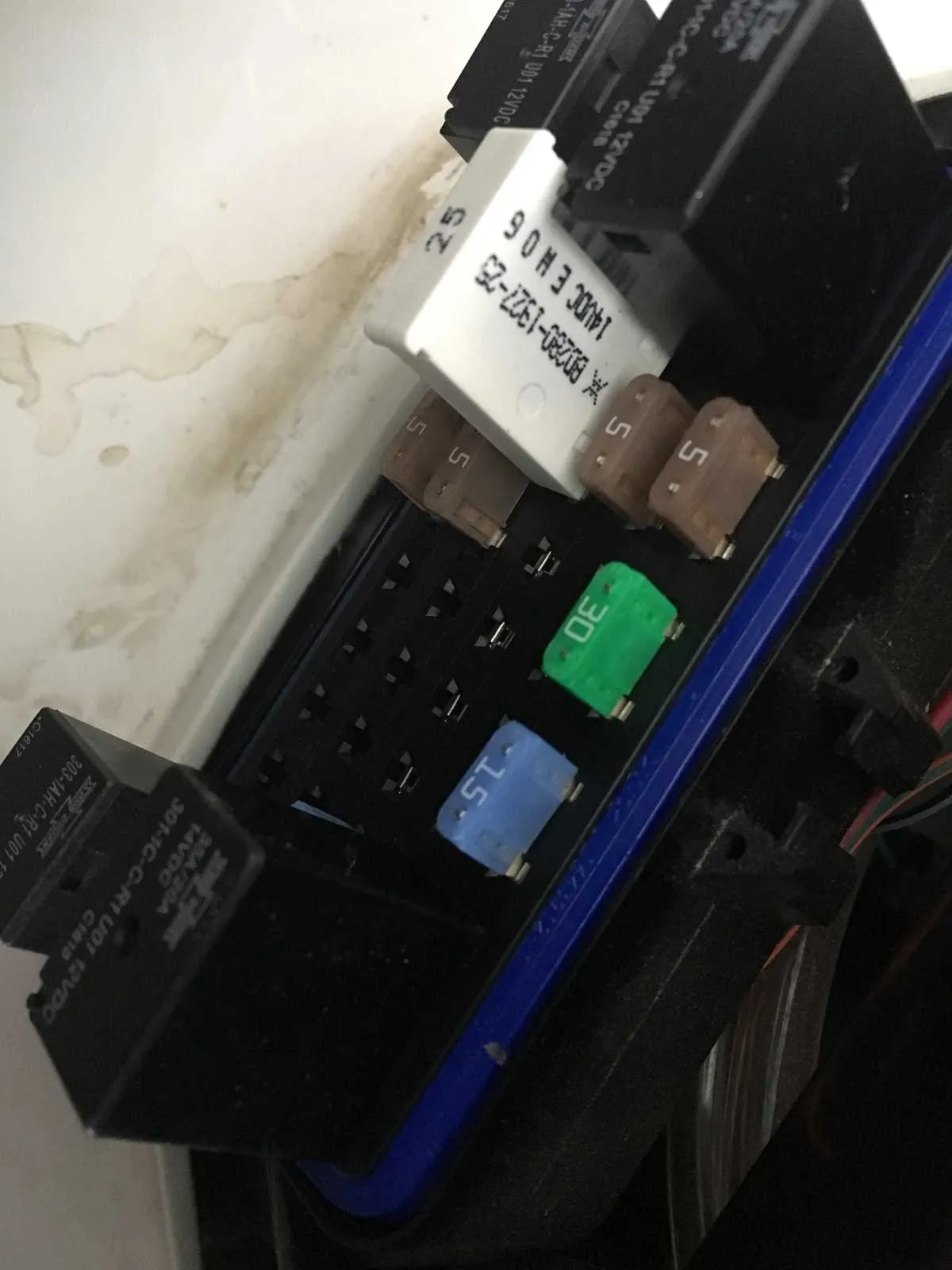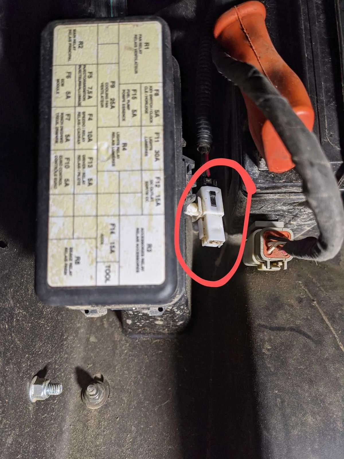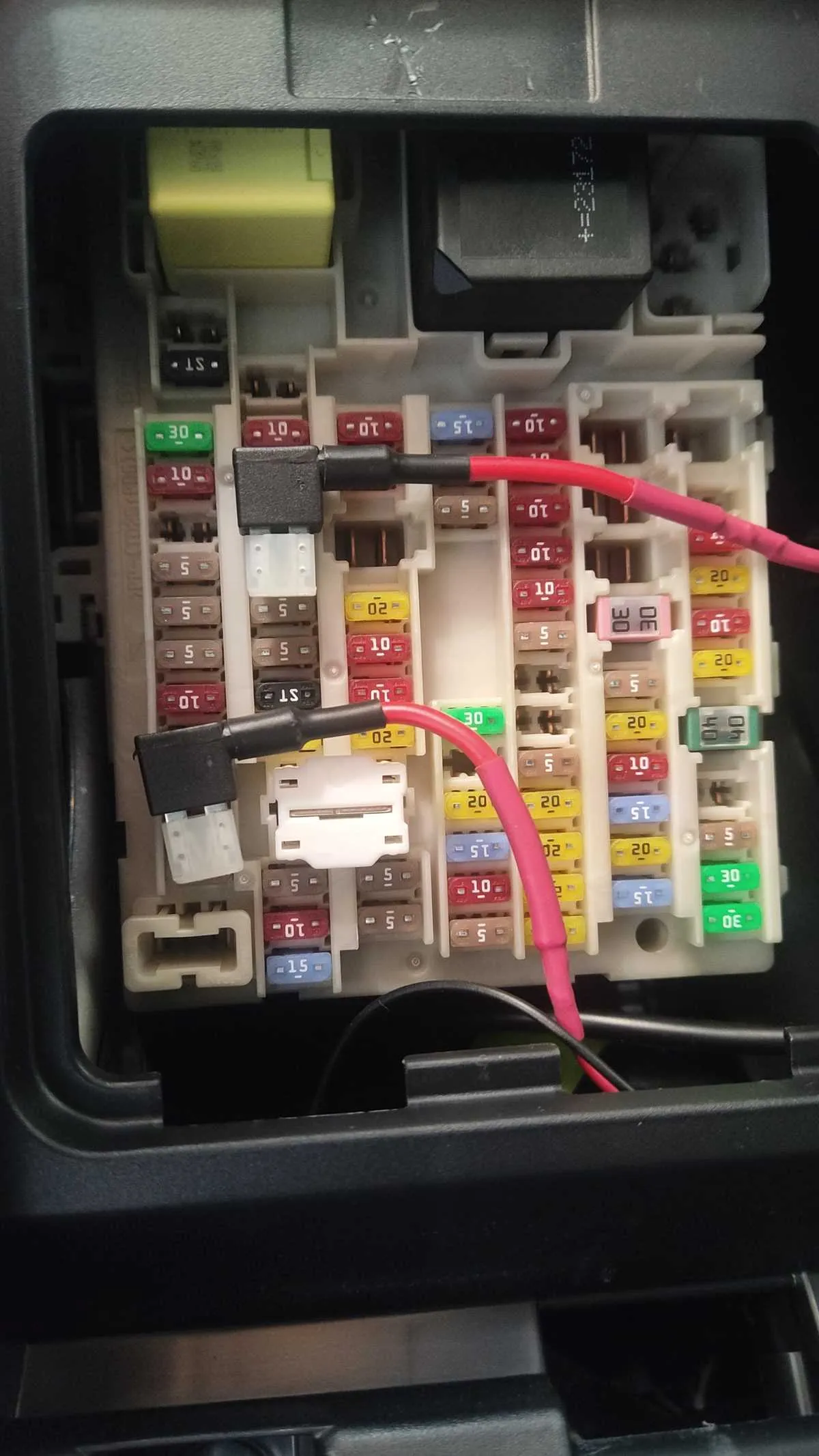
Begin by inspecting the relay compartment beneath the seat or front cargo panel–most models group protective elements there. Look for a black plastic cover secured with clips; beneath it, a labeled map indicates each circuit’s protection location.
For ignition issues, examine the slot labeled “IGN” or marked with a lightning bolt icon. It typically houses a 10A or 15A mini-blade component. Headlight failure usually traces back to a 15A unit marked with a bulb symbol. Power steering and instrument cluster errors often relate to 30A or 40A maxi-type protectors in a separate side panel.
Use needle-nose pliers to pull each piece one at a time. Test with a multimeter or replace with an identical-rated spare. Keep a set of 5A–40A replacements in the rear compartment storage. If relays are involved, tap lightly while the circuit is active to detect sticking.
Tip: Always disconnect the battery before manipulating electrical components. Avoid swapping identical-looking elements unless their amperage rating and function are confirmed by the legend on the plastic cover or user manual.
Can-Am Outlander Fuse Box Diagram
Access the electrical panel by removing the front storage compartment cover. Locate the black plastic housing positioned behind the right wheel well, secured with two Torx T30 screws. Use a flat-head screwdriver to gently pry open the cap, revealing the internal circuit protectors.
Refer to the label on the underside of the lid for slot identification. For example, position F5 typically controls the headlight relay, while F10 links to the ignition circuit. Use a multimeter to verify continuity before replacing any burnt elements. Always disconnect the battery prior to inspection.
If replacements are required, select mini-blade 10A or 15A types, depending on the original amperage rating. Avoid inserting higher-rated elements to prevent wiring damage. Store a set of spares in the glove compartment for trail-side repairs.
Fuse Locations by Model Year and Engine Type

For 2018 570cc models, the primary panel is mounted under the seat, adjacent to the ECM. Relays and protectors for the starter, fan, and lighting circuits are grouped together in a sealed module with labeled access.
In 2019–2020 versions with 650cc engines, the central power unit sits behind the right side panel, near the battery tray. The layout includes individual slots for EFI, ignition, and cooling systems, each identified by amp rating and symbol on the cover.
2021 models using 850cc powertrains position the control block beneath the front cargo compartment. High-draw circuits like winch and power steering are assigned separate inline protectors near the steering column, not housed in the main enclosure.
1000R variants from 2022 feature dual distribution hubs: one under the rear cargo platform for chassis electronics, and a second mini-block in the front panel managing engine and sensor circuits. Each housing contains blade-style interrupters with amperage engraved on the plastic body, simplifying field replacement.
In 2023 models with 700cc setups, the protective array was relocated to a vertical slot behind the left wheel well. This shift reduced water exposure and allows tool-free access to ECM-linked connections, including injection and throttle regulation lines.
Functions of Each Component in the Primary Power Distribution Unit
Verify the purpose of each protected circuit using the cover legend or owner’s manual. Below is a detailed list of typical assignments found in the main compartment:
- IGN (15A–30A): Powers ignition switch and related start-up electronics.
- EPS (30A): Supplies current to electronic power steering controller.
- EFI (15A): Controls fuel injection module and engine sensors.
- FAN HI/LO (20A–30A): Regulates radiator cooling fans through relay switching for thermal management.
- 4WD/VCM (15A–25A): Drives four-wheel-drive system actuators and vehicle control modules.
- ECU (10A–15A): Maintains stable voltage for the central control unit.
- INJ (10A): Activates fuel injector circuits under ECM command.
- HORN (10A–15A): Linked to audible alert system via steering column button.
- ACC (10A–15A): Connects power outlets and auxiliary accessories.
- LIGHT HI/LO (15A–20A): Manages front beam output via dual-function switches.
Relays within this section enable high-load operations without overloading switchgear:
- Starter Relay: Engages motor cranking circuit upon ignition signal.
- Main Relay: Activates ECM and associated electronic modules.
- Cooling Relay: Triggers radiator fan stages based on sensor input.
- Power Relay: Distributes voltage to major subsystems post-ignition.
- Light Relay: Handles high amperage for headlights and auxiliary lamps.
Always disconnect the battery before servicing any protected terminal. Replace blown elements with identical amperage values to avoid circuit overload.
Steps to Access and Replace Electrical Protectors Safely Without Dealer Tools

Locate the protective housing under the dashboard or near the battery compartment. Use a flat-head screwdriver or your fingers to gently pry open the cover without damaging clips.
Disconnect the main power source before handling any components to prevent short circuits or shocks. Remove the negative terminal from the battery using a standard wrench.
Identify the faulty electrical safeguard by consulting the user manual’s legend or markings on the underside of the housing cover. Compare amperage ratings to ensure the replacement matches the original.
Use needle-nose pliers or a fuse puller from a basic toolkit to extract the defective element. Pull it straight out to avoid bending or breaking terminals.
Insert a replacement with the same rating firmly into the slot, ensuring full contact with the metal connectors inside. Avoid forcing mismatched sizes, which can cause damage or electrical failure.
Close the protective enclosure by snapping the lid back into place, making sure all clips are secure to prevent dust or moisture ingress.
Reconnect the battery’s negative terminal and test the electrical system by starting the engine and checking affected circuits for proper operation.
Regular inspection of these components extends reliability and prevents unexpected power interruptions.