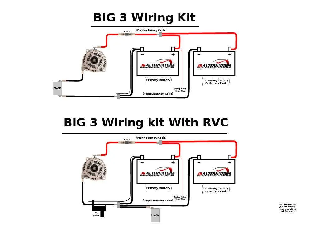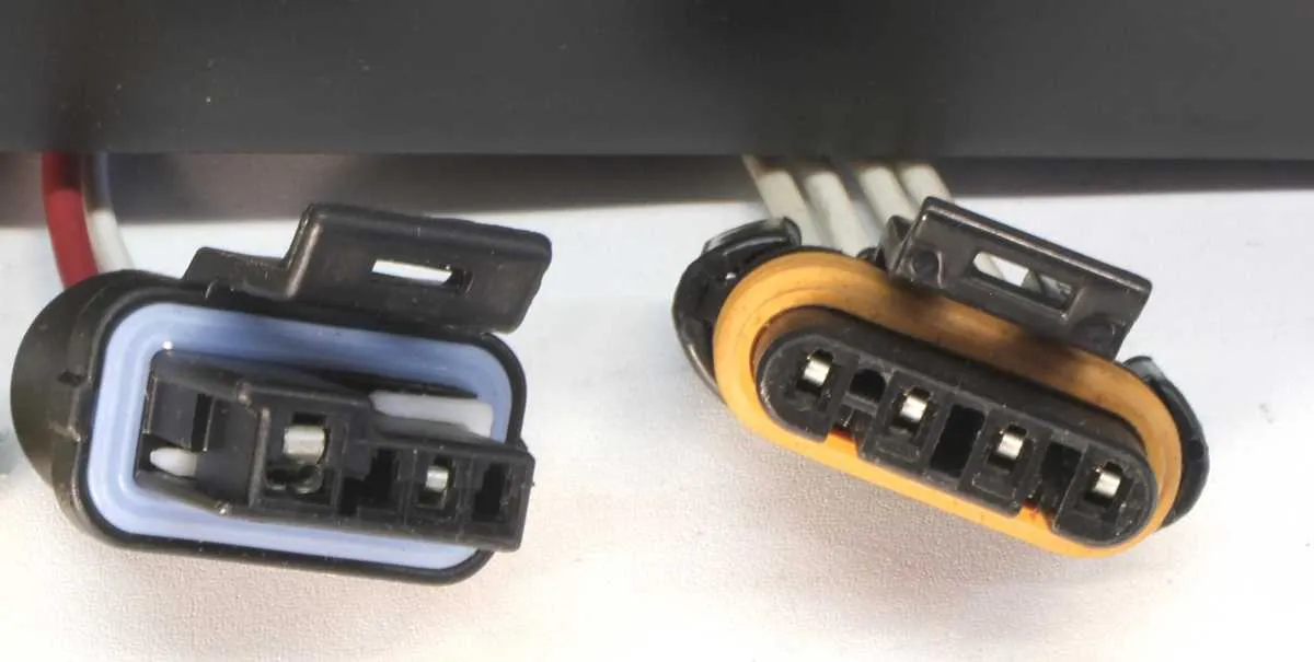
If you’re working on a GM vehicle’s electrical system, it’s crucial to understand the proper setup for the 4-pin connection to the generator. The 4-pin setup typically includes essential components such as the voltage regulator, ground, and signal leads. Incorrect connections can lead to underperformance or even complete failure of the system.
First, ensure that the ground pin is securely attached to the vehicle’s frame to provide a solid return path for current. Next, the field connection regulates the magnetic field and should be properly linked to the voltage controller. This pin typically requires a stable, low-resistance connection to maintain proper charge levels.
The excitation lead is responsible for starting the charging process once the engine is running. Make sure this pin is linked directly to the ignition system or a specific control module, depending on your vehicle’s design. Finally, the charging output pin should be connected to the battery, ensuring that the vehicle’s power supply remains consistent and reliable.
By double-checking each of these connections and making sure that they are securely fastened, you can prevent electrical issues that might arise from improper installation or wear over time. A thorough understanding of these key points will improve system reliability and ensure long-term performance.
GM 4 Pin Power Generator Connection Overview

Ensure the proper placement of each lead to guarantee optimal performance of the unit. The four main connections on the system are typically labeled for simplicity:
- Terminal 1: Connects to the vehicle’s electrical system to supply power.
- Terminal 2: Responsible for monitoring the charging status and controlling voltage levels.
- Terminal 3: Provides the path for ground, ensuring safe electrical flow.
- Terminal 4: Usually integrates with the vehicle’s control system for additional monitoring and feedback.
Proper identification of each terminal before making connections is crucial. Double-check the labeling to avoid incorrect assembly and potential damage to sensitive components. Always use the recommended gauge for each terminal to ensure safe and efficient operation.
Tip: If experiencing issues with system charging, verify that the terminal supplying feedback is correctly connected, as it plays a key role in regulating voltage levels.
Understanding the Key Wires and Their Functions
The first connection is typically the output terminal, which delivers power from the generator to the battery and other components. This lead should be routed to the vehicle’s power distribution system, ensuring a solid connection for optimal performance.
The second essential connection is the ground terminal. It provides a return path for current, completing the circuit. It’s crucial to ensure that this terminal is securely attached to a metal part of the vehicle’s frame for reliable operation.
Next, the exciter terminal plays a vital role in initiating the charging process. It carries a small current from the vehicle’s ignition system to the generator, activating it when the engine starts. Ensure this terminal is linked to a controlled switch to prevent unnecessary power draw when the engine is off.
Finally, the sensing terminal monitors the voltage level of the electrical system, adjusting output based on demand. It should be linked to the vehicle’s voltage regulator to maintain consistent system voltage and prevent overcharging or undercharging the battery.
How to Properly Connect the GM 4 Wire Alternator in Your Vehicle
Ensure the connections are secure and precise when attaching the GM 4-wire generator to your vehicle’s electrical system. Follow these steps carefully:
- Identify the four terminals: You’ll have a terminal for the main output, a terminal for the field control, one for the ground, and the final one for the signal or sense line.
- Main output terminal: Connect the thickest cable to the large terminal that provides the charge. This leads to the battery and is responsible for the power transfer.
- Field control terminal: Attach this to the regulator circuit. It controls the amount of voltage generated. Ensure the connection is stable to avoid inconsistent charging performance.
- Ground connection: Use a short, direct path to ground. This is critical to ensure the system functions properly, reducing the risk of electrical shorts or overheating.
- Signal or sense line: This line is used by the voltage regulator to monitor the battery’s charge level. Route it carefully to prevent any voltage fluctuations.
- Double-check connections: After securing each terminal, make sure no loose ends or exposed metal are visible. Tighten all connections to the manufacturer’s specifications to avoid any electrical failures.
Testing the system is crucial. Once everything is connected, start the engine and use a multimeter to verify that the voltage reading is correct at the battery terminals, typically between 13.8V and 14.4V. Adjust the regulator if necessary for optimal performance.
Troubleshooting Common Issues with GM 4 Wire Alternator Wiring

If you’re experiencing charging problems, start by checking the voltage output from the regulator. Use a multimeter to confirm that it’s within the expected range, typically 13.5 to 14.5 volts when the engine is running. If the voltage is too low, it could indicate a malfunctioning regulator or a faulty connection.
Next, inspect the connections at the terminal marked “B+” for tightness and corrosion. Loose or corroded contacts here can prevent proper current flow, causing intermittent or failed charging. Clean and re-secure the terminal if necessary.
Verify the ground connection between the engine block and the battery. A poor or broken ground will often lead to erratic performance or no charging at all. This is one of the most common causes of electrical issues, so ensure it’s clean and tight.
If your system is showing overcharging, check the connection to the voltage sensing terminal. A faulty or disconnected sensing line can cause the voltage regulator to misread the system voltage, leading to excessive output.
In cases where the system isn’t producing any power, inspect the diode trio and rectifier for faults. A failure here can cause the output to drop to zero. If you suspect damage, replacement of the internal components may be required.