For an effective braking system in GM vehicles, it’s crucial to understand how the brake pressure is managed between the front and rear axles. One of the key components responsible for this task is a pressure regulator, which ensures optimal brake balance. By adjusting the hydraulic force based on vehicle load, it prevents rear wheel lock-up during hard braking.
To properly install and troubleshoot these units, you need to familiarize yourself with their flow characteristics. Typically, these systems operate with a specific configuration where the front brakes receive a higher pressure than the rear. This setup is essential for maintaining stability and preventing skidding under heavy braking conditions.
When dealing with these brake systems, always check the pressure settings and the sequence of operations. Incorrect calibration can lead to uneven brake performance, compromising vehicle safety. For accurate diagnostics, consult the manufacturer’s service manual and inspect the hydraulic components for wear and tear.
Key considerations: Always verify the correct installation orientation of the pressure regulator, as improper placement can result in incorrect pressure distribution. Additionally, regular maintenance ensures that the system remains efficient and responsive, especially in high-performance situations or during extreme conditions.
Proper knowledge of brake system dynamics, combined with precise adjustments, will significantly enhance braking efficiency and overall vehicle control.
GM Brake Pressure Control System Schematic

For optimal braking performance and safety, it is essential to understand the GM brake pressure regulation mechanism. This component ensures an even distribution of braking force between the front and rear axles, preventing lock-up and improving handling during braking. The system uses a specific pressure regulator that balances fluid flow to maintain ideal brake pressure according to vehicle load.
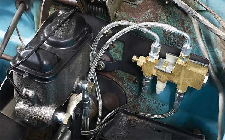
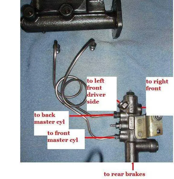
To identify the key elements of this system, start with the master cylinder, which is the primary source of brake fluid. The regulator is positioned between the master cylinder and the brake lines leading to the rear brakes. It modulates fluid pressure by using a spring-loaded piston or a mechanical lever, depending on the model. In certain designs, the regulator also incorporates a sensor to adjust pressure dynamically based on vehicle speed and load distribution.
Important steps for system inspection: Ensure the regulator is correctly calibrated to match the brake system’s specifications. Misadjustment can lead to uneven braking or reduced effectiveness under heavy loads. Regularly check the lines for leaks, and inspect the springs or mechanical components for wear.
When repairing or replacing the pressure control mechanism, always refer to the vehicle’s specific maintenance manual. GM uses different configurations based on the model and year of production. Check for any modifications or updates in the design that may impact system functionality.
Key considerations for troubleshooting: If the rear brakes lock up under normal conditions or if braking efficiency is inconsistent, the issue might lie with the brake pressure control system. Ensure that no debris or corrosion has affected the fluid passage and that the regulator is free from damage.
The system’s role is critical in achieving proper brake balance. Understanding its operation and maintenance is crucial for ensuring both safety and vehicle performance.
How to Read a GM Brake System Pressure Distribution Diagram

Start by identifying the two main sections: the front and rear brake lines. These lines will typically be shown with distinct labels or color codes to differentiate the distribution of pressure between the front and rear brakes.
- Look for the control mechanism, often indicated as a cylindrical component in the diagram, positioned between the master cylinder and the rear brake lines.
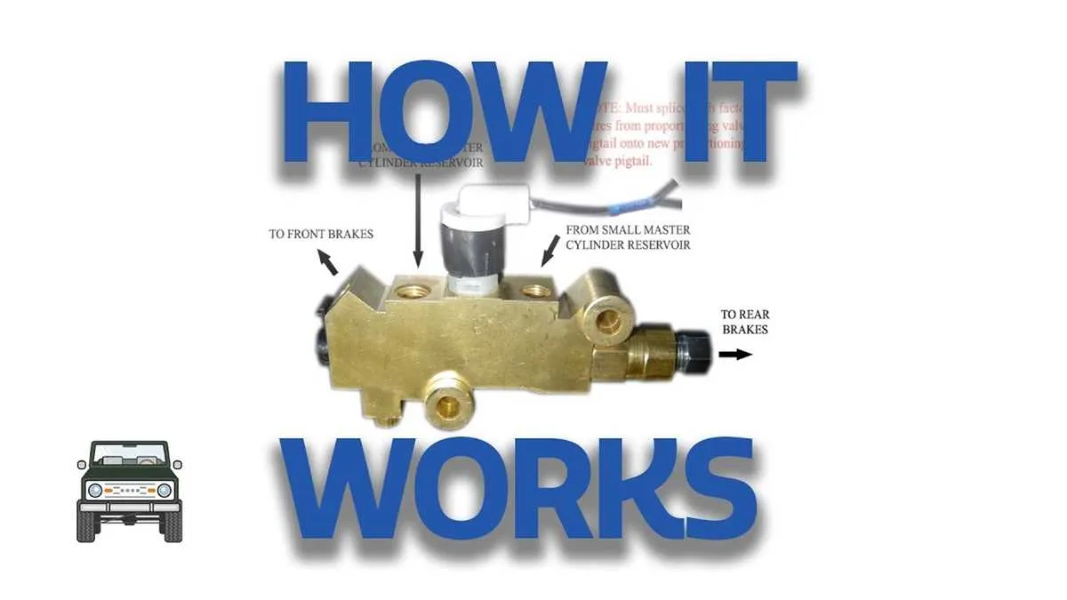
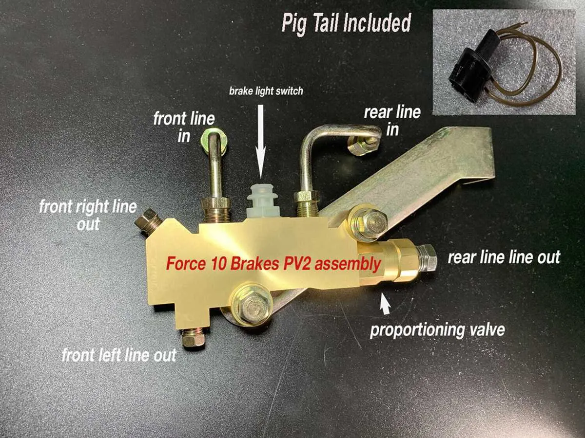
- Next, check the inlet and outlet points. The inlet corresponds to the master cylinder, while the outlet directs pressure to the rear brakes. This flow ensures that pressure is appropriately regulated based on vehicle load and driving conditions.
- Examine the pressure release spring, typically represented by a coil. It regulates pressure when the braking force exceeds a certain threshold, ensuring proper force balance.
- Focus on the set pressure values, which may be provided as numeric values or pressure ranges. These values indicate the maximum permissible pressure directed to the rear brakes under normal driving conditions.
For accurate operation, make sure the components are connected properly, ensuring that the flow of hydraulic fluid is uninterrupted and follows the intended paths shown in the visual. Misalignment or incorrect routing can lead to uneven braking or system failure.
Finally, review any additional annotations or instructions that may explain specific features or special conditions, such as different pressure settings for various GM models.
Step-by-Step Guide to Identifying Components in a GM Proportioning Valve Diagram

To identify the various parts in the GM hydraulic pressure control system layout, follow these steps:
| Component | Description | Location in Diagram |
|---|---|---|
| Master Cylinder Input | Receives pressure from the brake pedal, sending fluid to the system. | Usually positioned at the top left of the schematic. |
| Pressure Reducing Mechanism | Adjusts fluid pressure to ensure balanced braking force between front and rear brakes. | Typically appears as a central component connected to the master cylinder input. |
| Rear Brake Line | Directs fluid to the rear brakes, influenced by pressure regulation. | Connected to the pressure reducing mechanism and marked with a line going towards the rear brake assembly. |
| Front Brake Line | Transports fluid to the front brakes, generally under higher pressure. | Connected directly to the master cylinder input, usually on the left side. |
| Spring | Helps in balancing and resetting the pressure regulating system. | Typically located near the central area of the schematic, often adjacent to the pressure control component. |
| Fluid Return Path | Allows the system to return excess fluid to the reservoir once pressure is relieved. | Marked with a returning line leading from the brake system back to the master cylinder. |
Use this reference to pinpoint and trace the flow of hydraulic fluid through the layout. Pay attention to the connections and direction of the lines, as these indicate how each part interacts with others to control braking force.
Troubleshooting Common Issues with GM Brake Balancing Systems
When dealing with issues in GM braking systems, one of the first steps is to inspect the flow control mechanism. If you’re facing inconsistent braking or improper pressure distribution, ensure that the adjustment mechanism is not clogged or stuck. Debris or corrosion in these components can significantly affect performance.
If the braking pressure is not balanced correctly between front and rear circuits, verify the alignment of the pressure reducing valve. Misalignment or wear could cause uneven brake force application. Additionally, check for any damage to the internal springs that regulate pressure distribution, as they may cause improper functioning.
Another common issue involves hydraulic leaks. Inspect all connections, especially around the distribution block, for leaks that could lead to loss of pressure or inconsistent braking. Tightening fittings or replacing faulty seals can often resolve this issue.
Finally, if there’s an unusual change in pedal feel or braking responsiveness, ensure the system is bled properly. Air in the brake lines can cause erratic behavior, and it’s crucial to remove all air pockets from the entire system to restore normal operation.