Properly connecting the components of your ignition setup is essential for reliable engine performance. Ensure that each part of the ignition circuit is connected according to manufacturer specifications to avoid misfires or electrical failures. Follow the pinout mapping closely for correct alignment of the coil, trigger, and other critical elements.
Power supply management is one of the most crucial aspects of the setup. The power leads to the coil must be securely connected, with adequate insulation to prevent shorts. Verify that the grounding is correct to avoid poor spark generation. Use a multimeter to check voltage continuity across all key connections.
Next, ensure that the trigger signal from the control unit reaches the ignition module correctly. This step is vital to ensure the spark is fired at the right time. Double-check each terminal for corrosion or damage, which can disrupt signal flow. A faulty connection here can lead to ignition timing issues, significantly affecting engine operation.
Lastly, always confirm the connection integrity between the coil and the spark plugs. Faulty connections here can prevent the spark from reaching the combustion chamber, leading to misfires. Using high-quality, durable wiring materials will provide long-term reliability and enhance the system’s overall efficiency.
Understanding the Electrical Connections
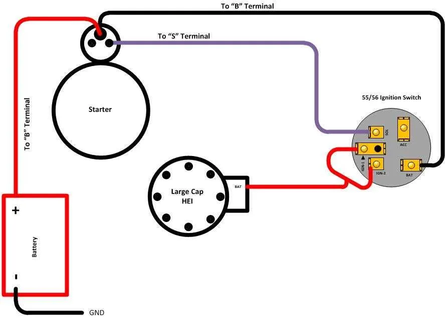
To ensure optimal performance of the ignition system, correctly identifying and connecting the components is crucial. The central unit, responsible for triggering the spark, should be connected to the power supply using a proper voltage wire. This wire should come from the vehicle’s battery or fuse box, depending on your setup.
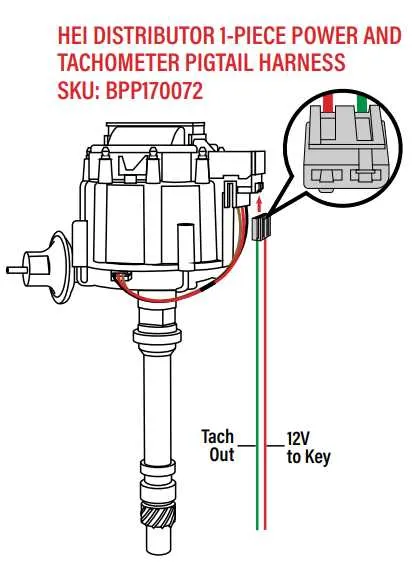
1. Power Supply: Use a 12V wire from the battery or fuse block to provide consistent power to the central unit. Make sure this wire is thick enough to handle the load without significant voltage drops.
2. Signal Wire: The signal wire connects the central ignition system to the control module. This wire carries a pulse, which triggers the firing sequence. Make sure the signal wire is routed away from power cables to avoid interference.
3. Grounding: A solid ground connection is essential to prevent electrical noise and ensure proper function. The ground wire should be attached to the engine block or the frame of the vehicle.
4. Coil Connections: If using an ignition coil, the positive terminal should be connected to the output terminal of the unit. The negative terminal connects to the points or the control module, depending on your configuration.
5. Timing Adjustment: Ensure that the unit is mounted in the correct position, with the timing being adjusted precisely to align with engine specifications. Any misalignment could result in engine misfires or inefficient combustion.
Remember: Double-check all connections for corrosion, loose terminals, or damaged insulation, as these issues could cause malfunctions or even system failure.
Identifying Key Pins in the Hei Distributor Wiring

When connecting the ignition system, it’s essential to accurately identify the key terminals for proper functionality. Here are the most important pins to focus on:
- Pin 1: This is the power input pin, usually connected to the positive terminal of the ignition coil. It powers the system and ensures the coil receives necessary voltage.
- Pin 2: This terminal serves as the ground connection, crucial for completing the circuit and ensuring proper signal grounding for the system to work efficiently.
- Pin 3: The signal output pin connects to the control module or the tachometer. It sends timing signals that synchronize engine rotation with ignition timing.
- Pin 4: The bypass pin, usually linked to the ignition switch. When the engine is cranking, this terminal allows full voltage for better performance before the system stabilizes.
- Pin 5: This is the trigger pin for the ignition control module, responsible for initiating spark at the right moment based on engine timing data.
Ensure each connection is secure and properly routed to avoid misfires and inefficient ignition performance. Incorrect pin identification can lead to system failures, engine hesitation, or electrical shorts.
Connecting the Ignition Component to the System
To ensure proper function, the ignition module needs a reliable 12V power source from the battery. Connect the positive terminal of the ignition coil to the power supply, ensuring secure contact to avoid voltage drops. The coil’s negative terminal must be linked to the control unit, which will regulate the timing and firing sequence.
Next, establish a solid ground connection between the ignition unit and the engine block. This prevents electrical interference and maintains system stability during operation. Verify the grounding point is free of corrosion and properly secured for optimal performance.
The signal from the ignition control unit should be routed through a high-quality cable to the spark plug terminals. Use wires rated for high-voltage applications to prevent degradation over time. Ensure each connection is tight and insulated to avoid shorts or sparks.
Lastly, integrate the tachometer output from the ignition system, if required, into the dashboard for accurate RPM monitoring. This is a simple connection, usually made to a dedicated terminal on the control unit.
Troubleshooting Common Wiring Issues with Hei Distributors

Check the coil connections first. If the ignition system is malfunctioning, ensure the positive and negative terminals are correctly connected to the ignition module and coil. Misconnections here can lead to weak or no spark. Use a multimeter to verify that the coil is receiving adequate power from the ignition switch.
Inspect the ground wire. A poor ground can cause erratic performance or complete failure. Ensure the ground connection is clean, tight, and free of corrosion. It’s often a simple issue but crucial for proper signal flow.
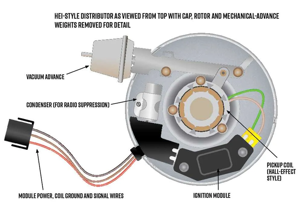
Examine the module for loose or broken connections. Even slight disconnections or corrosion at the terminals can cause intermittent issues. Tighten or replace any faulty connectors and check continuity with a multimeter.
Check for damage to the pickup coil wiring. Any shorts or open circuits here will disrupt the signal and prevent the system from operating correctly. Make sure the pickup coil is properly aligned with the reluctor and there are no signs of wear or damage.
Verify that the timing is set correctly. Misadjusted timing can mimic wiring issues by causing misfires or poor engine performance. Use a timing light to confirm alignment with the manufacturer’s recommended settings.
Test the fuse and relays. A blown fuse or malfunctioning relay can prevent the ignition system from receiving power. Inspect the fuse box for blown fuses and replace them as needed.
Use dielectric grease on all connections to protect against moisture and corrosion. Over time, environmental factors can cause electrical failure if contacts aren’t properly sealed.
Finally, check for signs of overheating or wear on the components. Worn-out parts may indicate an underlying issue in the electrical connections, which can be addressed by replacing the faulty components.